
Three-dimensional frequency domain controllable source numerical simulation method

A numerical simulation, frequency domain technology, applied in CAD numerical modeling, electrical digital data processing, special data processing applications, etc. Improve work efficiency and improve the effect of solving efficiency

Active Publication Date: 2018-09-07
CENT SOUTH UNIV
View PDF2 Cites 13 Cited by
  • Summary
  • Abstract
  • Description
  • Claims
  • Application Information

AI Technical Summary

Problems solved by technology

[0008] (1) The vector finite element method uses infinite boundary conditions, so that its calculation area is not only large, but also because it contains air layers, the condition number of the linear equations formed is poor. When using iterative method to solve, the efficiency is often low, and it becomes lower with frequency The number of iterations needs to increase continuously, which reduces the computational efficiency;
[0009] (2) When using the vector finite element method, the electric field value of the measuring point often needs to be obtained by interpolation of the grid nodes around the measuring point, which affects the accuracy
[0011] (1) When using the integral equation method, when the current source and the electromagnetic field measuring point are at the same position, there will be singularity, and it is difficult to obtain high-precision calculation results;
[0012] (2) The coefficient matrix formed by the integral equation method is full rank and dense. After the large-scale area is divided, the large dense matrix formed is difficult to solve and the efficiency is low;
[0013] (3) The pulse basis function used in the integral equation method, the precondition is that the electric field in the subdivided unit is uniform, which is not applicable to the high conductivity contrast difference model

Method used


Image

  • Three-dimensional frequency domain controllable source numerical simulation method
  • Three-dimensional frequency domain controllable source numerical simulation method
  • Three-dimensional frequency domain controllable source numerical simulation method

Examples


Embodiment Construction

[0047] The accompanying drawings constituting a part of the present application are used to provide further understanding of the present invention, and the exemplary embodiments of the present invention and their descriptions are used to explain the present invention and do not constitute an improper limitation of the present invention.

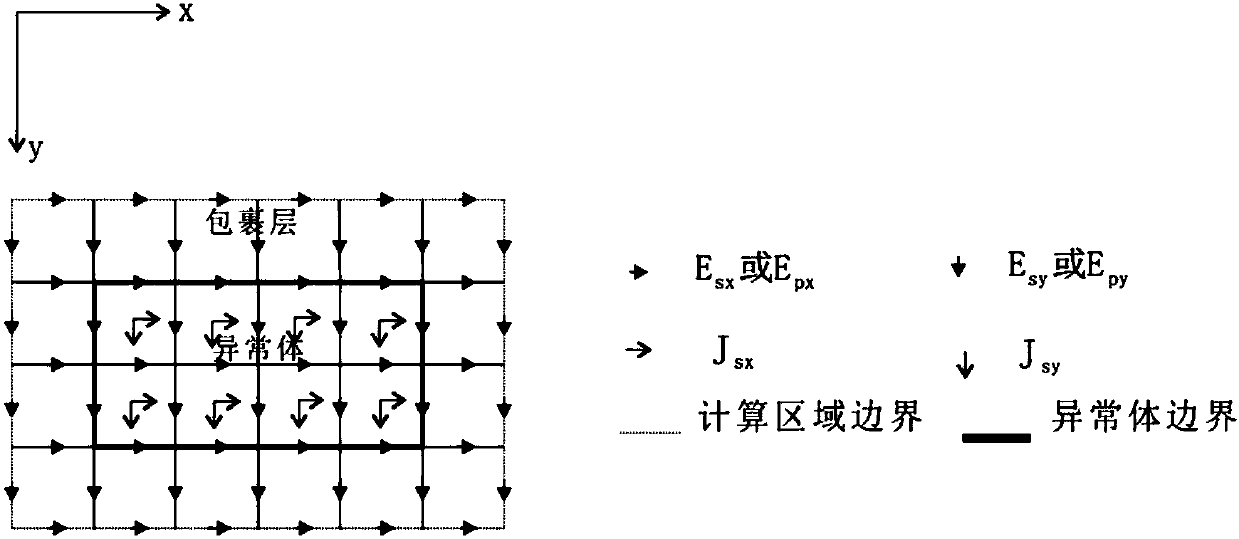
[0048] see figure 1 , the three-dimensional frequency-domain controllable source numerical simulation method provided by the present invention includes the following steps:

[0049] Step S100: define the calculation area in the resistivity anomaly body and its adjacent wrapping layer, and divide it into a plurality of regular unit bodies;

[0050] Step S200: Calculate the initial electric field under the excitation condition of the artificial source, use the weighted margin method to establish a finite element equation system at the midpoint of the edge of the unit body in the calculation area, and use node rearrangement to decompose the coef...


PUM


Abstract

The invention provides a three-dimensional frequency domain controllable source numerical simulation method. The method comprises the steps of S100: defining a calculation region in a resistivity anomaly body and an adjacent wrapping layer, and dividing the calculation region into multiple regular unit bodies; S200: calculating an initial electric field under an artificial source excitation condition, and by adopting a weighted residual method, establishing a finite element equation set of edge midpoints of the unit bodies in the calculation region; S300: defining an observation point as a boundary node by using a Green function, and enabling a secondary electric field of an internal node to express a secondary electric field of the boundary node; S400: substituting a Green function expression into a mixed equation set to obtain a first equation set only about the secondary electric field of the internal node; and S500: solving the first equation set to obtain secondary electric fieldvalues of nodes comprised in the unit bodies. According to the method, a vector finite element method and a volume integral equation method are applied; the calculation region is reduced; the calculation amount is reduced; the calculation precision is improved; formed equations are sparse in coefficient matrix and good in condition number; and a calculation result is accurate.

Description

technical field [0001] The invention relates to the technical field of controllable source electromagnetic method forward modeling, in particular to a three-dimensional frequency domain controllable source numerical simulation method. Background technique [0002] Compared with the natural source, the controllable source electromagnetic method has the characteristics of strong anti-interference ability and high efficiency compared with the electromagnetic field generated by the artificial source. Controlled source electromagnetic method work area has been developed to land, sea, aviation and underground. Controlled source electromagnetic method has been widely used in various periods of engineering survey, geothermal resource development, metal mining, oil exploration and other fields. [0003] The controllable source electromagnetic method can simulate the observation data corresponding to different geological conditions, analyze the morphological characteristics of the co...

Claims


Application Information

Patent Timeline
IPC IPC(8): G06F17/50
CPCG06F30/23G06F2111/10
Inventor 柳建新刘嵘柳卓
Owner CENT SOUTH UNIV
Learn More