
Direct torque control method for a three-phase four-switch permanent magnet synchronous motor speed control system

A technology of permanent magnet synchronous motor and direct torque control, which is applied in motor control, motor generator control, AC motor control, etc. It can solve the problems of limited control accuracy, large fluctuations in torque and flux linkage, and affecting motor performance, etc. problems, to achieve the effect of improving running performance and precise torque control

Active Publication Date: 2018-09-07
广东爱吉尔机器人科技有限公司
View PDF4 Cites 5 Cited by
  • Summary
  • Abstract
  • Description
  • Claims
  • Application Information

AI Technical Summary

Problems solved by technology

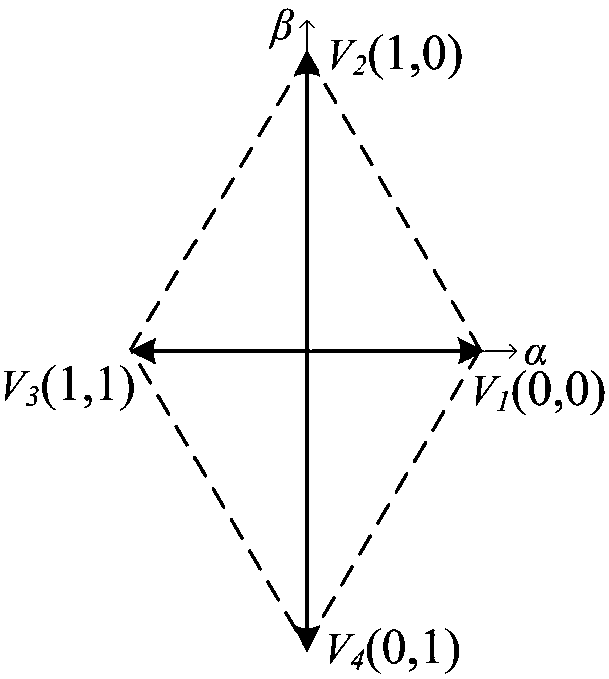
Compared with the three-phase six-switch inverter, the three-phase four-switch inverter topology can only generate four basic voltage vectors, and their magnitudes are not exactly the same
Therefore, the traditional direct torque control method of three-phase four-switch permanent magnet synchronous motor based on the switch vector table has limited control accuracy, and the fluctuation of torque and flux linkage will also become larger, which will affect the performance of the motor, so it is necessary to improve it

Method used


Image

  • Direct torque control method for a three-phase four-switch permanent magnet synchronous motor speed control system
  • Direct torque control method for a three-phase four-switch permanent magnet synchronous motor speed control system
  • Direct torque control method for a three-phase four-switch permanent magnet synchronous motor speed control system

Examples


Embodiment Construction

[0032] The specific implementation manners of the present invention will be described below in conjunction with the accompanying drawings.

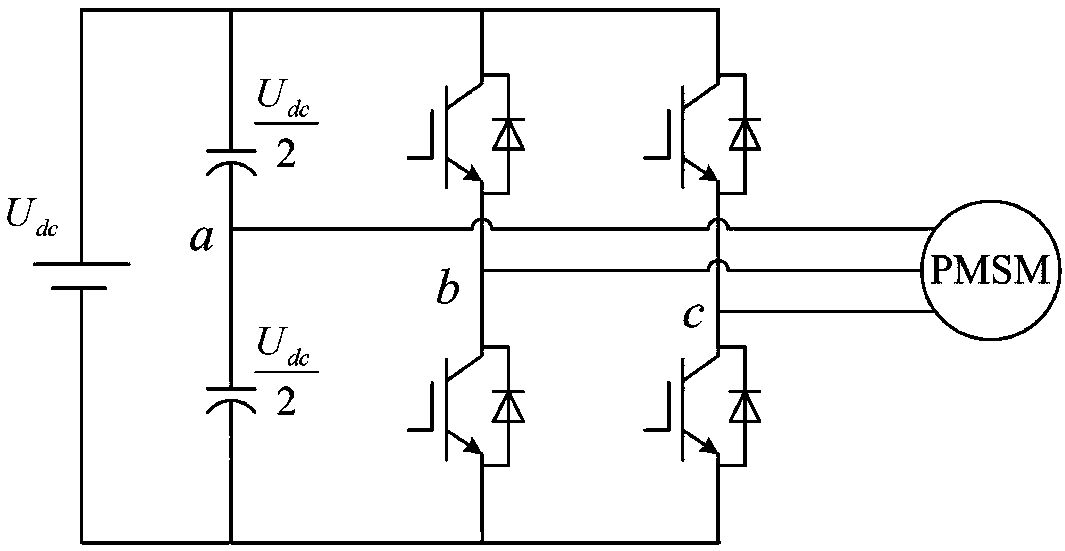
[0033] figure 1 It is a structural diagram of the power main circuit of the three-phase four-switch inverter driving the permanent magnet synchronous motor speed control system implemented in the patent of the present invention. Such as figure 1 As shown, phase B and phase C of the motor are connected to the two-phase normal bridge arms of the inverter, and phase A is connected to the neutral point of the DC capacitor.

[0034] with S x (x=B, C) represents the switching state of the power switch tube on the two-phase bridge arms of B and C, S x =1 when the upper tube of the bridge arm is on and the lower tube is off, S x =0, when the lower tube of the bridge arm is turned on, the upper tube is turned off. The four switching tubes on the two-phase bridge arm have four switching states, and four basic voltage vectors V 1 , V 2 , V 3...


PUM


Abstract

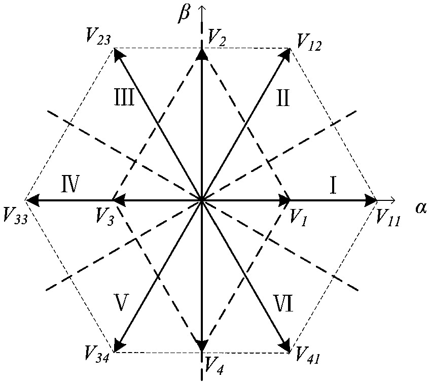
The invention provides a direct torque control method for a three-phase four-switch permanent magnet synchronous motor (PMSM) speed control system, comprising a step 1 of reconstructing six basic voltage vectors by using four unbalanced voltage vectors generated by a three-phase four-switch inverter; a step 2 of obtaining the position of the PMSM, and calculating the motor speed to obtain a reference torque given value Te; a step 3 of calculating a motor stator flux and a feedback torque, taking the motor torque and the stator flux as control objects to obtain output voltage components usq andusd; a step 4 of obtaining a reference voltage vector us according to the voltage components usq and usd, determining the sector of the voltage vector us, using a reconstructed effective voltage vector and a zero voltage vector in the sector as an alternative voltage vector, selecting an evaluation function, substituting the alternative voltage vector into the evaluation function G, and obtainingan output voltage vector ui by minimizing the evaluation function G. The method can achieve a precise torque control effect.

Description

technical field [0001] The invention relates to a direct torque control method of a three-phase four-switch permanent magnet synchronous motor speed regulating system, belonging to the field of motor control. Background technique [0002] The direct torque control method of permanent magnet synchronous motor has the advantages of simple control structure and fast dynamic response, and is widely used in daily life and industrial production. Usually, the permanent magnet synchronous motor direct torque control speed regulation system is fed by a three-phase six-switch voltage source inverter. In order to reduce the number of switching tubes and reduce the hardware cost and power consumption of the drive system, the three-phase four-switch inverter motor drive system has received more and more attention. In addition, when a fault occurs in a phase bridge arm of the three-phase six-switch inverter, such as short circuit or open circuit, the reliability of the drive system can b...

Claims


Application Information

Patent Timeline
IPC IPC(8): H02P21/00H02P25/022
CPCH02P21/0003H02P2207/05H02P25/024
Inventor 宁博文周凤星卢少武严保康马娅婕但峰胡轶
Owner 广东爱吉尔机器人科技有限公司
Learn More