
Nondestructive testing device in manufacturing process

A non-destructive testing and manufacturing process technology, used in manufacturing tools, measuring/indicating equipment, metal processing mechanical parts, etc., can solve the problems of slow debugging and adjustment process, such as difficulty in one step, waste of resources, etc., to ensure coaxiality , to ensure the accuracy requirements, to ensure the effect of stability

Inactive Publication Date: 2018-09-11
浦江县速达进出口有限公司
View PDF0 Cites 15 Cited by
  • Summary
  • Abstract
  • Description
  • Claims
  • Application Information

AI Technical Summary

Problems solved by technology

[0002] At present, in the field of gear processing, gear hobbing is the most important link, which directly affects the progress of subsequent processes. In the process of gear hobbing, the span distance of hobbing will change due to the influence of machine tool accuracy and temperature. , At this time, it is necessary to re-measure the span distance and then adjust the program according to the span distance measurement. It is difficult to complete the adjustment process in one step, and it needs to be debugged step by step. After the hobbing is clamped, due to the reason of the measuring ball, It is necessary to remove the workpiece from the fixture for measurement, because repeated clamping will cause rotten teeth and knife damage. Generally, unqualified workpieces cannot be processed and tested again, which wastes resources, and there are also cases where the workpiece is not removed for measurement. The method is to smear butter on the measuring ball, so that the measuring ball is absorbed in the tooth surface. This measurement method is difficult to operate and the measurement is not accurate.

Method used


Image

  • Nondestructive testing device in manufacturing process
  • Nondestructive testing device in manufacturing process
  • Nondestructive testing device in manufacturing process

Examples


Embodiment Construction

[0013] The following will clearly and completely describe the technical solutions in the embodiments of the present invention with reference to the accompanying drawings in the embodiments of the present invention. Obviously, the described embodiments are only some, not all, embodiments of the present invention. Based on the embodiments of the present invention, all other embodiments obtained by persons of ordinary skill in the art without making creative efforts belong to the protection scope of the present invention.

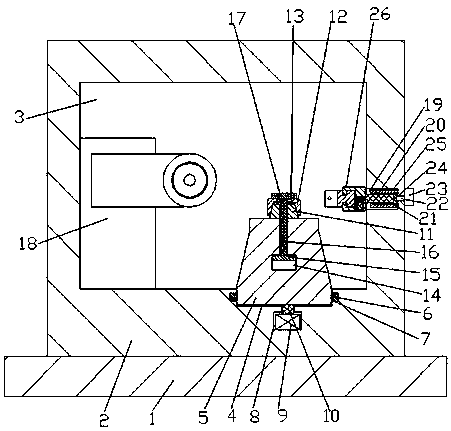
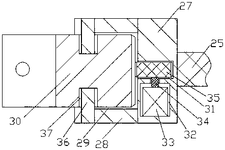
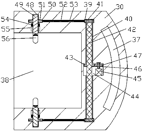
[0014] see Figure 1-4, an embodiment provided by the present invention: a non-destructive testing device in the manufacturing process, including a fixed base plate 1, the upper end surface of the fixed base plate 1 is provided with a CNC cabinet 2 with an integrated structure with it, and the inside of the CNC cabinet 2 A processing space 3 is provided, and the right side of the lower end wall of the processing space 3 is provided with a clamp groove 4, and a...


PUM


Abstract

The invention discloses a nondestructive testing device in the manufacturing process. The nondestructive testing device comprises a fixed bottom plate; a numerical control case is arranged on the upper end face of the fixed bottom plate, and the fixed bottom plate and the numerical control case are of an integrated structure; a clamp is arranged in a clamp groove; the middle of the upper end faceof the clamp is fixedly connected with a conical shaft; the upper side of the conical shaft is sleeved with an expanding sleeve; a hob module is fixedly arranged at the left end inside a machining space; and the left end of a telescopic rod penetrates out of the left end wall of a telescopic space and a telescopic groove to be fixedly connected with a span ranging testing device. During working ofthe nondestructive testing device, it is guaranteed that the expanding sleeve can be uniformly expanded towards the periphery through a partition groove, the coaxiality is guaranteed, the accuracy requirement in the machining process is guaranteed, the measurement angle is automatically adjusted, and the accuracy of the measurement value is guaranteed; and in the measurement process, workpieces during machining do not need to be removed, the tooth rotting phenomenon caused by repeated clamping is avoided, machining raw materials are saved, and technical controllability is improved.

Description

technical field [0001] The invention relates to the field of processing process control, in particular to a non-destructive testing device in the manufacturing process. Background technique [0002] At present, in the field of gear processing, gear hobbing is the most important link, which directly affects the progress of subsequent processes. In the process of gear hobbing, the span distance of hobbing will change due to the influence of machine tool accuracy and temperature. , At this time, it is necessary to re-measure the span distance and then adjust the program according to the span distance measurement. It is difficult to complete the adjustment process in one step, and it needs to be debugged step by step. After the hobbing is clamped, due to the reason of the measuring ball, It is necessary to remove the workpiece from the fixture for measurement, because repeated clamping will cause rotten teeth and knife damage. Generally, unqualified workpieces cannot be processe...

Claims


Application Information

Patent Timeline
IPC IPC(8): B23Q17/00B23Q17/20
CPCB23Q17/00B23Q17/20
Inventor 朱林祥
Owner 浦江县速达进出口有限公司
Features
  • Generate Ideas
  • Intellectual Property
  • Life Sciences
  • Materials
  • Tech Scout
  • Unparalleled Data Quality
  • Higher Quality Content
  • 60% Fewer Hallucinations
Learn More