Power battery heat management system and method for electric vehicle

A thermal management system and power battery technology, applied in electric vehicles, batteries, secondary batteries, etc., can solve the problems of poor cooling effect, poor heat dissipation effect, obvious cooling effect, etc., and achieve the effect of heating

Inactive Publication Date: 2018-09-11
CHERY AUTOMOBILE CO LTD
View PDF7 Cites 22 Cited by
  • Summary
  • Abstract
  • Description
  • Claims
  • Application Information

AI Technical Summary

Problems solved by technology

[0005] On the one hand, the convective heat transfer coefficient between the air and the surface of the power battery is low, while the heat conduction path inside the power battery is long, the thermal resistance is large, and the heat dissipation effect is poor, and the front end of the power battery can preferentially contact the low-temperature air, so its cooling effect Obviously, the cooling effect of the

Method used


Image

  • Power battery heat management system and method for electric vehicle
  • Power battery heat management system and method for electric vehicle

Examples


Embodiment 1

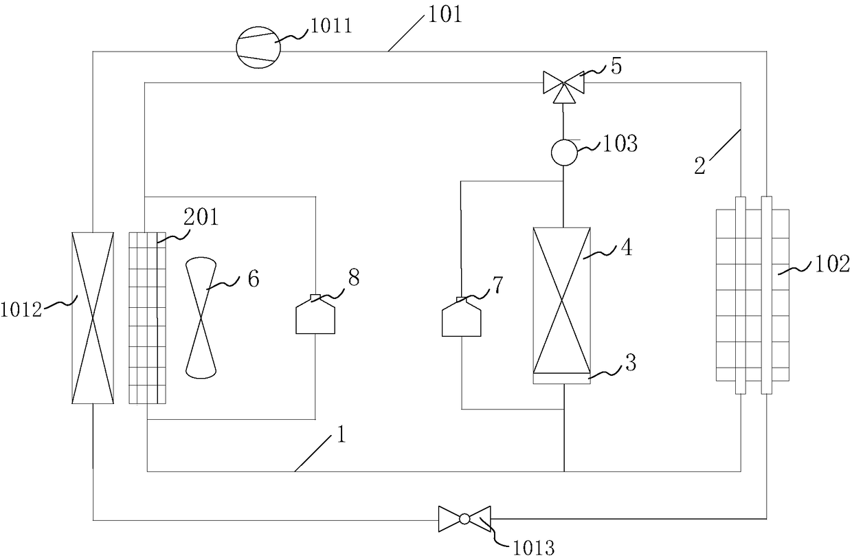
[0052] An embodiment of the present invention provides a thermal management system for a power battery of an electric vehicle, the structural diagram of which is shown in figure 1 As shown, the electric vehicle power battery thermal management system includes: a first cooling circuit 1 , a second cooling circuit 2 and a heating film 3 .

[0053] Wherein, the first cooling circuit 1 is suitable for cooling the power battery 4 whose temperature is higher than the first threshold value through the coolant, and the first cooling circuit 1 includes a refrigeration exchanger 102 and a water pump 103 connected with an air-conditioning refrigerant circulation branch 101. The refrigerant circulation branch 101 is provided with a compressor 1011 and a condenser 1012;

[0054] The second cooling circuit 2 is suitable for cooling the power battery 4 whose temperature is higher than the second threshold and lower than the first threshold through the coolant, and the second cooling circuit ...

Embodiment 2

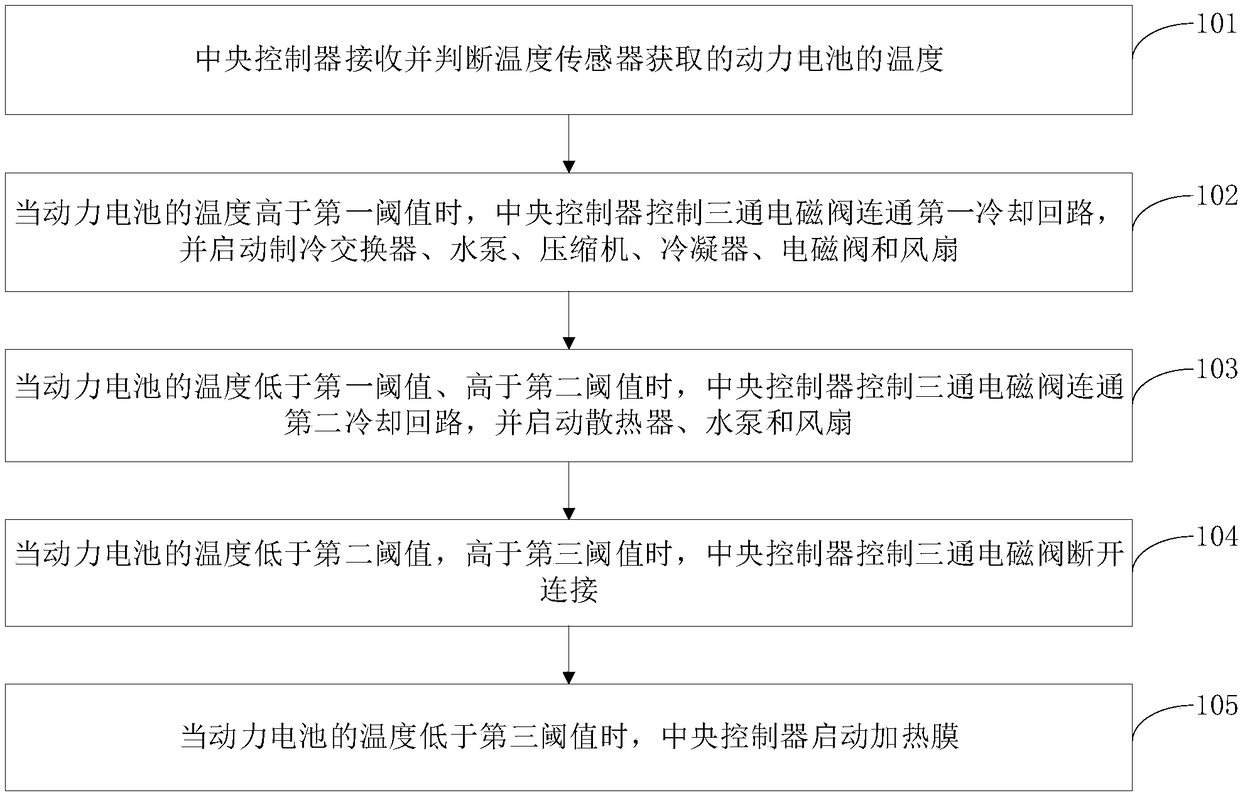
[0082] An embodiment of the present invention provides a thermal management method for a power battery of an electric vehicle, which is combined with a thermal management system for a power battery of an electric vehicle to realize thermal management of the power battery 4. The flow chart of the method is as follows figure 2 As shown, the details are as follows:

[0083] Step 101: the central controller receives and judges the temperature of the power battery 4 obtained by the temperature sensor;

[0084] Specifically, the temperature sensor can sense the temperature of the power battery 4 in real time, regardless of whether the power battery 4 is in a charging state or a discharging state.

[0085] It should be noted that the temperature sensor measures the average temperature of the power battery 4 .

[0086] Step 102: When the temperature of the power battery 4 is higher than the first threshold, the central controller controls the three-way solenoid valve 5 to communicat...


PUM


Abstract

The invention discloses a power battery heat management system and method for an electric vehicle, and belongs to the technical field of power battery heat management. When the temperature of a powerbattery is higher than a first threshold value, a first cooling circuit is connected, a cold medium gets to a condenser and then gets to a refrigeration exchanger through a compressor to conduct heatexchange with refrigerant, so that the cooled refrigerant enters the power battery for heat exchange, and it is achieved that the power battery is cooled in a high-temperature environment; when the temperature of the power battery is higher than a second threshold value and lower than the first threshold value, a second cooling circuit is connected, the refrigerant enters the power battery for heat exchange after being cooled by a cooler, and it is achieved that the power battery is subjected to liquid cooling at a general environment temperature; when the temperature of the power battery is lower than a third threshold value, a heating membrane is started, the power battery is heated up through heating of the heating membrane, and it is achieved that the power battery is heated in a low-temperature environment.

Description

technical field [0001] The invention relates to the technical field of thermal management of power batteries, in particular to a thermal management system and method for a power battery of an electric vehicle. Background technique [0002] With the acceleration of social and economic development, the demand for energy is increasing, and the application of new energy technologies in various fields is getting louder and louder. Currently in the automotive industry, technicians have developed electric vehicles powered by electricity. Among them, as the energy storage device and power source of electric vehicles, the power battery is a key component of electric vehicles, and its performance directly affects the performance of electric vehicles, such as power, driving range, driving performance, safety, etc. The electrochemical reaction and internal resistance in the power battery are very sensitive to temperature changes, which can easily affect the capacity, mileage, service l...

Claims


Application Information

Patent Timeline
IPC IPC(8): B60L11/18H01M10/613H01M10/615H01M10/625
CPCB60L58/26B60L58/27B60L2240/545H01M10/613H01M10/615H01M10/625H01M2220/20Y02E60/10Y02T10/70
Inventor 马文明程红杨鹏程源苗东卢生林
Owner CHERY AUTOMOBILE CO LTD
Why Eureka
Try Eureka