
Integrated heat dissipation type motor system

A technology that integrates heat dissipation and blowing fans. It is used in electrical components, electromechanical devices, and electric components. It can solve the problems of difficult to meet the requirements of heat exchange, low economy, and difficult maintenance, and achieve compact structure, reasonable layout, The effect of increasing power density

Active Publication Date: 2016-10-05
CHONGQING GENERAL IND (GRP) LTD
View PDF6 Cites 1 Cited by
  • Summary
  • Abstract
  • Description
  • Claims
  • Application Information

AI Technical Summary

Problems solved by technology

Although the effect of evaporative heat exchange is the best, it is difficult to maintain. For the blower fan, it is necessary to add a refrigerant circulation system, which is not economical; for the heat exchange of air alone, the heat exchange is difficult to meet the requirements; for the high-power magnetic levitation centrifugal drum The compressor still mainly uses coolant heat exchange and air heat exchange at the same time, in which the coolant flows in the cooling channel in the motor housing to bring out the heat of the stator winding, and the air is between the magnetic suspension bearing, the sensor, the rotor and the stator It flows in the gaps to bring out the internal heat of the components; however, in the conventional structure, an additional blower or induced draft fan needs to be installed on the air side to realize the air flow, and the heat exchanger connected to the cooling liquid side also needs to be installed with a fan to achieve Air-cooled, complex structure, high energy consumption, loud noise

Method used


Image

  • Integrated heat dissipation type motor system
  • Integrated heat dissipation type motor system

Examples


Embodiment Construction

[0011] The technical solution of the present invention will be described in detail below in conjunction with the accompanying drawings, so that those skilled in the art can better understand and implement the solution.

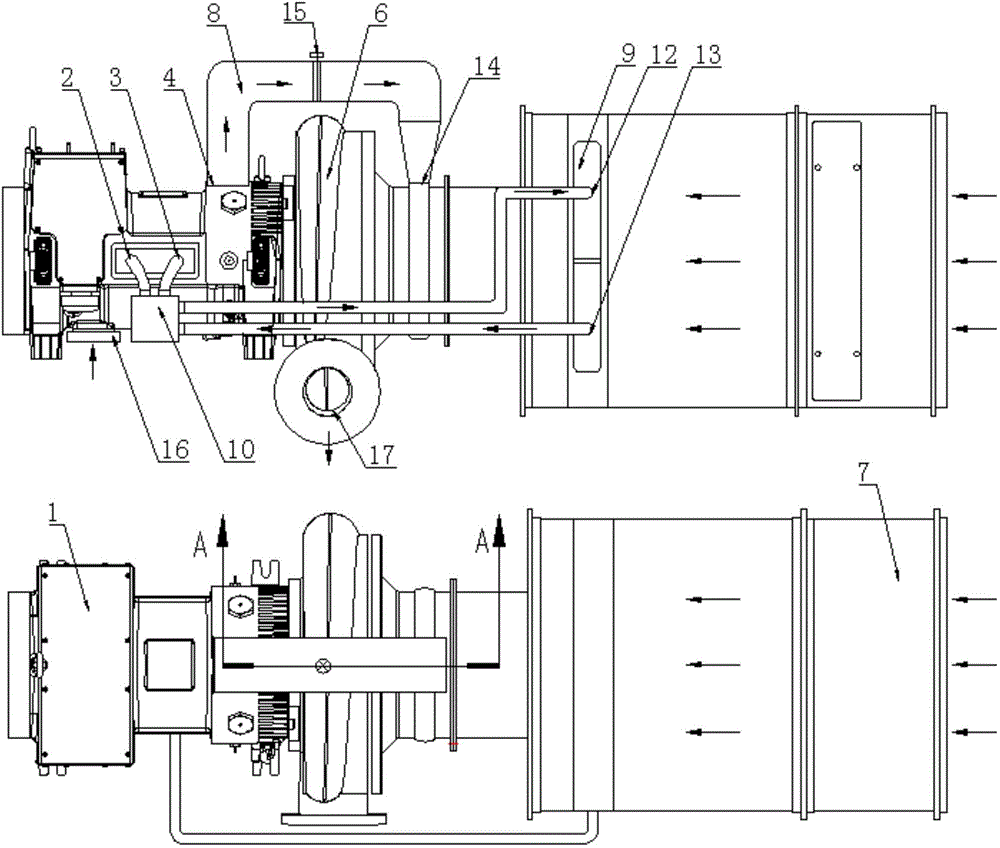
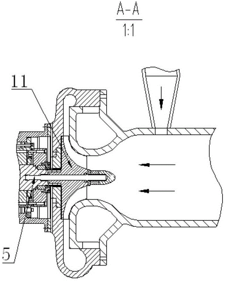
[0012] as attached figure 1 , attached figure 2 As shown, the integrated heat dissipation motor system includes a motor 1 with a coolant inlet 2, a coolant outlet 3, an air outlet 4 and a main shaft 5, and is characterized in that it also includes a blower fan 6, a filter muffler 7, an Air flow channel 8, heat exchanger 9, coolant circulation pump 10, impeller 11, motor 1 and pressure blower 6 are connected through flanges, impeller 11 is set on the main shaft 5 of motor 1, pressure blower 6 and filter silencer 7 Through the flange connection, the heat exchanger 9 is sealed and set in the filter muffler 7, and the coolant circulation pump 10 is respectively connected with the coolant inlet 2 and the coolant outlet 3 of the motor 1, and the coolant inlet A12 ...


PUM


Abstract

The invention relates to the technical field of motors, and provides an integrated heat dissipation type motor system. The integrated heat dissipation type motor system comprises a motor, a blower fan, a filtering muffler, an air-induced passageway, a heat exchanger, a cooling liquid circulation pump and an impeller, wherein the motor is connected with the blower fan by means of a flange, the impeller sleeves a main shaft of the motor, the air blower is connected with the filtering muffler by means of a flange, the heat exchanger is installed in the filtering muffler in a sealed and sleeved manner, the cooling liquid circulation pump is connected with a cooling liquid inlet and a cooling liquid outlet of the motor as well as a cooling liquid inlet A and a cooling liquid outlet B of the heat exchanger, and the air-induced passageway is connected with an air outlet of the motor and a volute air inducing port of the blower fan. The integrated heat dissipation type motor system realizes the compact structure and reasonable layout of the whole machine. Compared with the prior art, the integrated heat dissipation type motor system reduces adopted parts, increases power density of the whole machine, reduces power consumption of the whole machine, reduces operation noise of the unit, realizes the energy conservation and environmental protection, and improves production efficiency.

Description

technical field [0001] The invention relates to the technical field of motors, in particular to an integrated heat dissipation motor system. Background technique [0002] At present, the commonly used heat exchange methods for high-speed motors include air heat exchange, coolant heat exchange, and evaporation heat exchange. Although the effect of evaporative heat exchange is the best, it is difficult to maintain. For the blower fan, it is necessary to add a refrigerant circulation system, which is not economical; for the heat exchange of air alone, the heat exchange is difficult to meet the requirements; for the high-power magnetic levitation centrifugal drum The compressor still mainly uses coolant heat exchange and air heat exchange at the same time, in which the coolant flows in the cooling channel in the motor housing to bring out the heat of the stator winding, and the air is between the magnetic suspension bearing, the sensor, the rotor and the stator It flows in the ...

Claims


Application Information

Patent Timeline
Patent Type & Authority Applications(China)
IPC IPC(8): H02K9/19H02K9/04
Inventor 陈立
Owner CHONGQING GENERAL IND (GRP) LTD
Learn More