
High-pressure oil-free air compressor

A technology of oil-free air compressors and air compressors, which is applied in the direction of supporting machines, mechanical equipment, and engine frames, etc., and can solve problems such as long time consumption, low efficiency, and large volume of air compressors

Active Publication Date: 2017-09-05
浙江永源机电制造有限公司
View PDF11 Cites 2 Cited by
  • Summary
  • Abstract
  • Description
  • Claims
  • Application Information

AI Technical Summary

Problems solved by technology

The pressure of the existing single-stage air compressor is usually up to 125psi. If you need to generate a higher pressure, you usually need to perform two-stage compression. However, with the two-stage compression method, it takes a long time to reach the specified pressure value, and the efficiency is low. The volume of the air compressor is large, and it is especially important that the existing single-stage air compressor is difficult to achieve a higher pressure value. The main reason is that the cylinder will generate a lot of heat during the movement, and the greater the pressure, the greater the heat, and the overheating will affect the cylinder. The structural strength and normal use, so if you want to increase the pressure through a single cylinder, you need to improve the overall heat dissipation of the air compressor

Method used


Image

  • High-pressure oil-free air compressor
  • High-pressure oil-free air compressor
  • High-pressure oil-free air compressor

Examples


Embodiment Construction

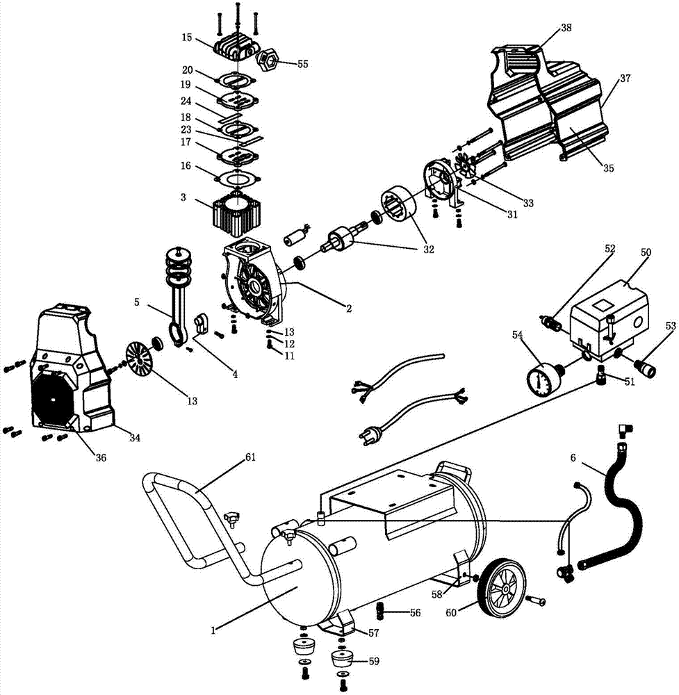
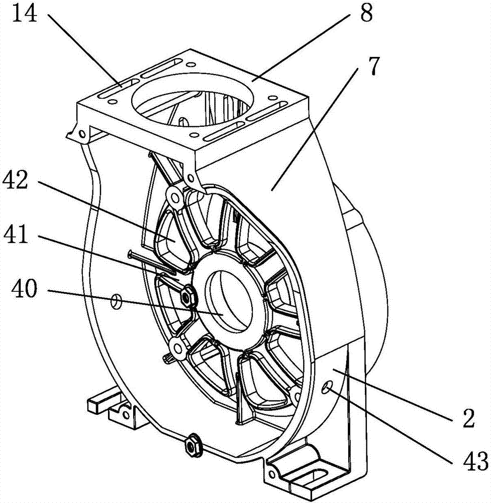
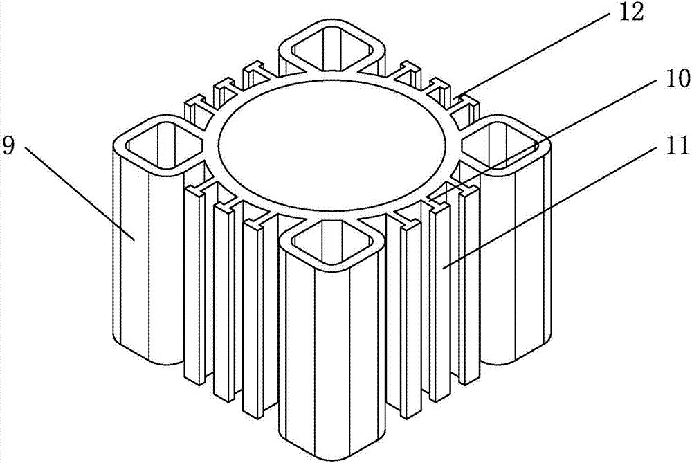
[0018] refer to Figures 1 to 4 The embodiment of a high-pressure oil-free air compressor of the present invention will be further described.

[0019] A high-pressure oil-free air compressor, comprising a connected main body of the air compressor and an air storage tank 1, the main body of the air compressor includes a connected crankcase 2 and a cylinder 3, the crankcase 2 is provided with a crankshaft 4, the crankshaft 4 is connected with a connecting rod 5 for driving the movement of the cylinder 3, and the air outlet of the cylinder 3 communicates with the air inlet of the air storage tank 1 through the high-pressure pipe 6. It is characterized in that: the crankcase 2 is provided with an extension 7, and the extension The cylinder block 8 for connecting with the cylinder 3 is provided on the part 7, and a number of fixed tubes 9 are arranged on the side of the cylinder 3. Strip-shaped first heat sink 10 between two adjacent fixed cylinders 9, one side of the first heat s...


PUM


Abstract

The invention discloses a high-pressure oil-free air compressor and belongs to the technical field of air compressors. The high-pressure oil-free air compressor aims to achieve a good mute effect and a high pressure value. The high-pressure oil-free air compressor is characterized by comprising an air compressor main machine and an air storage tank which are connected, wherein the air compressor main machine comprises a crankcase and an air cylinder which are connected, the crankcase is provided with an outward extension portion, the outward extension portion is provided with a cylinder seat connected with the air cylinder, the circumferential side of the air cylinder is provided with a plurality of fixing barrels, the fixing barrels are arranged in an annular array along the circumferential side of the air cylinder, the circumferential side of the air cylinder is further provided with a plurality of strip-shaped first cooling fins, each cooling fin is arranged between the two corresponding adjacent fixing barrels, one side of each first cooling fin is connected with the outer wall of the air cylinder, the other side of each first cooling fin is provided with a second cooling fin, the first cooling fins are perpendicular to the second cooling fins, a cooling flow channel is formed between every two adjacent first cooling fins, a crank is provided with a front fan arranged in the crankcase, and the cylinder seat is provided with air guide holes enabling the inner portion of the crankcase to communicate with the cooling flow channels.

Description

technical field [0001] The present invention relates to the technical field of an air compressor, more specifically, it relates to a high-pressure oil-free air compressor. Background technique [0002] The air compressor, referred to as the air compressor, is the main body of the air source device. It is a device that converts the mechanical energy of the prime mover into gas pressure energy, and is a pressure generating device for compressing air. [0003] The air compressor is a miniature reciprocating piston compressor. Its working principle is: when the motor uniaxially drives the crankshaft of the compressor to rotate, through the transmission of the connecting rod, the piston with self-lubrication without adding any lubricant will reciprocate. The working volume formed by the inner wall of the cylinder, the cylinder head and the top surface of the piston will change periodically. The pressure of the existing single-stage air compressor is usually up to 125psi. If you ...

Claims


Application Information

Patent Timeline
Patent Type & Authority Applications(China)
IPC IPC(8): F04B37/12F04B41/02F04B39/06F04B39/10F04B39/12F16M3/00
CPCF04B37/12F04B39/06F04B39/066F04B39/102F04B39/12F04B39/122F04B39/128F04B41/02F16M3/00
Inventor 王深广贺敬畏阮永幸
Owner 浙江永源机电制造有限公司
Learn More