
Head-mounted display device and heat dissipation mechanism thereof

A technology of heat dissipation mechanism and radiator, which is applied to structural parts of electrical equipment, cooling/ventilation/heating renovation, instruments, etc. The effect of heat accumulation

Active Publication Date: 2021-06-25
GOERTEK INC
View PDF14 Cites 1 Cited by
  • Summary
  • Abstract
  • Description
  • Claims
  • Application Information

AI Technical Summary

Problems solved by technology

[0004]However, on the one hand, because users often touch the housing when using the head-mounted display device, when the temperature of the housing is too high, it will cause discomfort such as scalding to the skin. Comfortable, resulting in a poor wearing experience of the product; on the other hand, due to the sealing requirements of the conventional casing, the heat generated by the heating element in the casing is easy to accumulate and cannot be quickly dissipated to the outside, resulting in poor heat dissipation efficiency, and the casing and The natural heat exchange efficiency of air is not high. To improve the heat exchange efficiency, it is necessary to increase the heat dissipation area of ​​the shell, resulting in a larger volume
In addition, although some head-mounted display devices use air-cooled heat dissipation in the casing, the air flow path is complicated, and it will be bent and turned many times in the casing, resulting in slow air flow and weakened heat dissipation efficiency.

Method used


Image

  • Head-mounted display device and heat dissipation mechanism thereof
  • Head-mounted display device and heat dissipation mechanism thereof
  • Head-mounted display device and heat dissipation mechanism thereof

Examples


Embodiment Construction

[0031] The following will clearly and completely describe the technical solutions in the embodiments of the present invention with reference to the accompanying drawings in the embodiments of the present invention. Obviously, the described embodiments are only some, not all, embodiments of the present invention. Based on the embodiments of the present invention, all other embodiments obtained by persons of ordinary skill in the art without making creative efforts belong to the protection scope of the present invention.

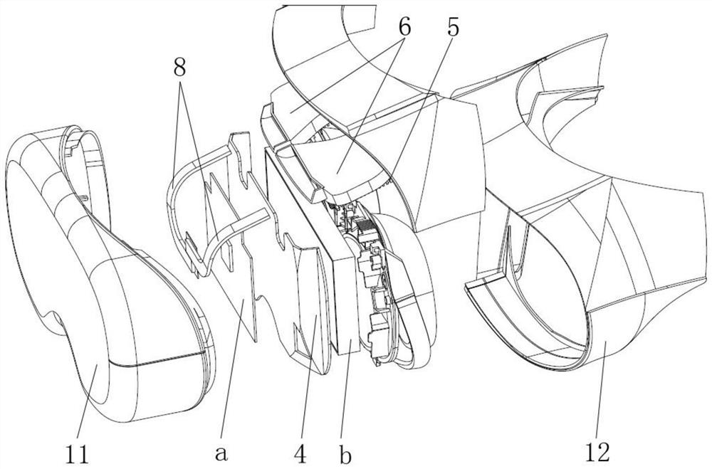
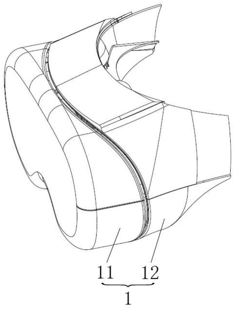
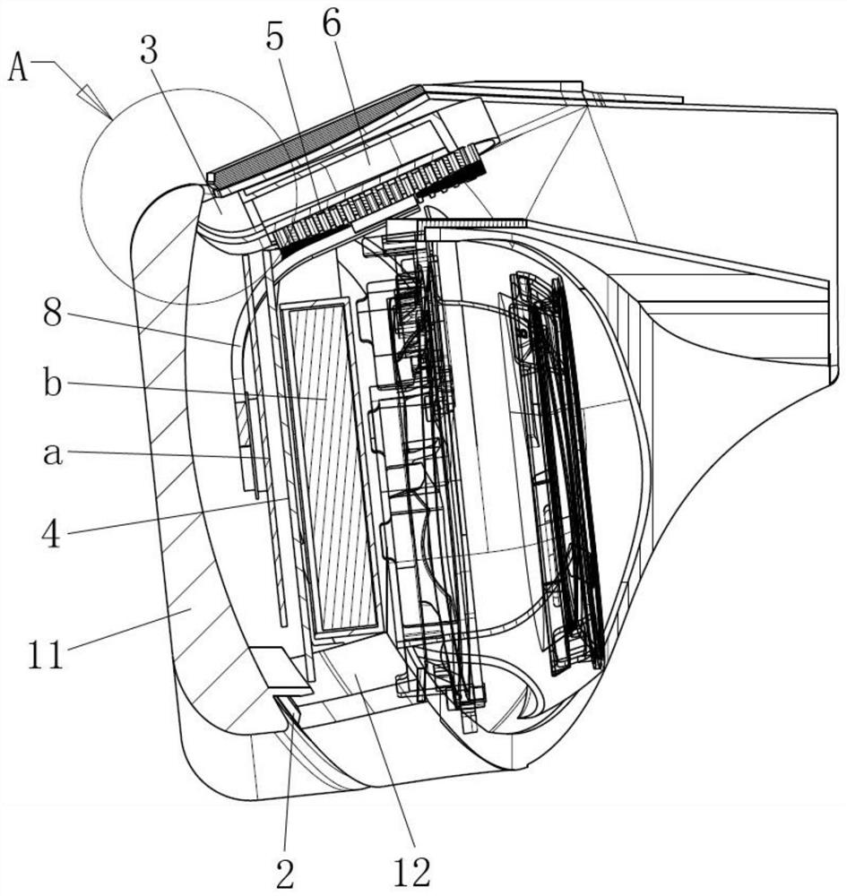
[0032] Please refer to figure 1 , figure 2 , image 3 , figure 1 It is a schematic diagram of the decomposition structure of a specific embodiment provided by the present invention, figure 2 for figure 1 The overall structure diagram of image 3 for figure 2 cutaway view. ,

[0033] In a specific embodiment provided by the present invention, the heat dissipation mechanism mainly includes an air inlet 2 , an air outlet 3 , a mounting plate 4 , a radi...


PUM


Abstract

The invention discloses a heat dissipation mechanism which comprises an air inlet formed in the bottom of a shell, an air outlet formed in the top of the shell, a mounting plate arranged in the shell and used for mounting a PCBA, a radiator arranged on the top of the mounting plate and used for dissipating heat of the PCBA, and a fan arranged on the top of the radiator and used for conducting forced convection heat dissipation on the radiator through airflow. A suction opening of the fan is communicated with the air inlet through the radiator, and an exhaust opening of the fan is communicated with the air outlet. Thus, by means of the air inlet formed in the bottom of the shell and the air outlet formed in the top of the shell, an almost-vertical air flow channel distributed in the vertical direction is formed in the shell, cold air can rapidly flow in the shell, heat exchange inside and outside the shell is rapidly completed, the air flow channel is simplified, and the air flow speed is increased. Meanwhile, heat can be dissipated to the outside in time, heat is prevented from being accumulated in the shell, and the size of the shell is prevented from being increased. The invention also discloses a head-mounted display device, which has the above beneficial effects.

Description

technical field [0001] The invention relates to the technical field of wearable devices, in particular to a heat dissipation mechanism. The present invention also relates to a head-mounted display device. Background technique [0002] With the development of virtual reality and augmented reality technologies, more and more head-mounted display devices have been widely used. [0003] At present, most head-mounted display devices use passive heat dissipation. The idea of ​​solving heat dissipation is basically to transfer the heat from heating elements such as PCBA and battery module to the casing, and then exchange heat between the casing and the outside air. This then dissipates heat into the air. [0004] However, on the one hand, because the user often touches the casing when using the head-mounted display device, when the temperature of the casing is too high, it will cause discomfort such as scalding to the skin, resulting in a poor wearing experience of the product; o...

Claims


Application Information

Patent Timeline
Patent Type & Authority Applications(China)
IPC IPC(8): G02B27/01H05K7/20H01M10/613H01M10/6554H01M10/6563
CPCG02B27/017G02B27/0176H05K7/20145H05K7/20172H05K7/20154H01M10/613H01M10/6554H01M10/6563Y02E60/10
Inventor 李小飞黄继硕刘焕洲姜滨迟小羽
Owner GOERTEK INC
Learn More