Cloth dyeing equipment

A dyeing equipment and fabric technology, applied in the field of fabric processing, can solve the problem of uneven dyeing, and achieve the effects of ensuring uniformity, preventing wrinkles and imprints, and speeding up the dyeing speed.

Pending Publication Date: 2018-09-11
重庆曹浩思瑗电子商务有限公司
View PDF0 Cites 22 Cited by
  • Summary
  • Abstract
  • Description
  • Claims
  • Application Information

AI Technical Summary

Problems solved by technology

[0004] The present invention intends to provide cloth dyeing equipment to solve the problem of un

Method used


Image

  • Cloth dyeing equipment

Examples


Embodiment Construction

[0019] The following is further described in detail by specific embodiments:

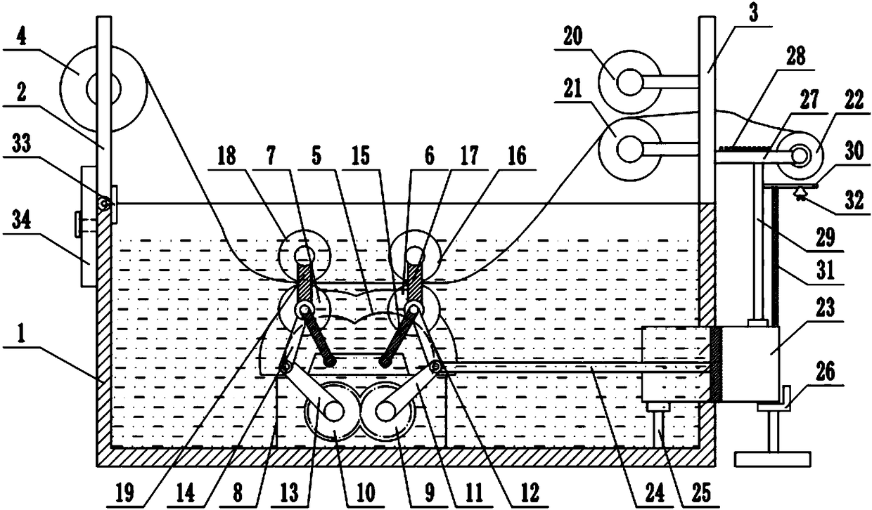
[0020] Reference numerals in the accompanying drawings include: dye tank 1, first support rod 2, second support rod 3, feed roller 4, chute 5, first transfer roller 6, second transfer roller 7, connecting plate 8 , driving gear 9, driven gear 10, driving rod 11, first link 12, driven rod 13, second link 14, limit rod 15, first pressure roller 16, first support rod 17, second Press roll 18, second support rod 19, upper squeeze roll 20, lower squeeze roll 21, discharge roll 22, cylinder 23, piston rod 24, support column 25, support table 26, support plate 27, air jet 28 , Support tube 29, slide plate 30, support spring 31, bell 32, inner abutment plate 33, outer abutment plate 34.

[0021] The example is basically as attached figure 1 Shown: cloth dyeing equipment, including a dye tank 1 with an upper opening, a first support rod 2 is connected to the left side of the upper end of the dye tank 1, an...


PUM


Abstract

The invention relates to cloth processing field and discloses cloth dyeing equipment. The cloth dyeing equipment comprises a dyeing tank, wherein a first support rod is rotationally connected to one side of the dyeing tank, a second support rod is fixedly connected to the other side of the dyeing tank, a feeding roll is rotationally connected to the first support rod, and a first transfer roll anda second transfer roll are movably connected to the inner wall of the dyeing tank; a driving gear and a driven gear are rotationally connected to the inner wall of the dyeing tank, the driven gear ismeshed with the driving gear, a driving rod is fixedly connected to the driving gear, a first connecting rod is rotationally connected to a free end of the driving rod, and a free end of the first connecting rod is rotationally connected to the first transfer roll; a driven rod is fixedly connected to the driven gear, a second connecting rod is rotationally connected to a free end of the driven rod, and a free end of the second connecting rod is rotationally connected to the second transfer roll; and a discharging roll is rotationally connected to one side of the second support rod, an air cylinder is fixedly connected to the side wall of the dyeing tank, and a piston rod of the air cylinder is rotationally connected to the driving rod. According to the cloth dyeing equipment, the problemthat the stacked cloth cannot be uniformly dyed by virtue of an existing dyeing machine during the dip dyeing is solved.

Description

technical field [0001] The invention relates to the field of fabric processing, in particular to fabric dyeing equipment. Background technique [0002] At present, the fabrics used for clothing, bed sheets, etc. are mostly dyed fabrics, and dyeing is an essential processing step in the processing of dyed fabrics. According to the different dyeing methods, fabric dyeing can be divided into coating dyeing and dip dyeing. Due to the problems of poor washing fastness, different light fastness and uneven dyeing of the dyed fabrics, the industry generally adopts the method of dip dyeing to dye the fabrics. [0003] The main working principle of dip dyeing is to set up a dye tank in the dyeing machine, and a large amount of dye liquor is placed in the dye tank. The fabric to be dyed is then dyed by dip dyeing. However, due to the action of gravity in the dye solution, the fabric is easily stacked in the dye tank, resulting in uneven dyeing. At the same time, because stacking is...

Claims


Application Information

Patent Timeline
IPC IPC(8): D06B3/20D06B15/00D06B15/02D06B23/04D06B23/20
CPCD06B3/206D06B15/00D06B15/02D06B23/04D06B23/205D06B3/18
Inventor 文化曹洪
Owner 重庆曹浩思瑗电子商务有限公司
Why Eureka
Try Eureka