Magnetic coupling type wireless charging system

A wireless charging and coupling technology, applied in the direction of circuits, inductors, current collectors, etc., can solve the problem of not being able to effectively improve the efficiency of magnetic coupling wireless charging, so as to improve wireless charging efficiency, increase magnetic permeability, and improve system transmission efficiency effect

Inactive Publication Date: 2018-09-11
SHANGHAI INST OF TECH
View PDF2 Cites 8 Cited by
  • Summary
  • Abstract
  • Description
  • Claims
  • Application Information

AI Technical Summary

Problems solved by technology

[0003] Magnetic coupling wireless charging technology is the mainstream technology of wireless charging at present. Reducing magnetic field leakage is the most effective way to improve the efficiency of magnetic coupling wireless charging. In the existing technology, the structural method of adding magnetic isolation sheets to the coil is mostly used to reduce the leakage of magnetic field. , but this technology can only play a certain role in blocking magnetic flux leakage, and cannot effectively improve the efficiency of magnetic coupling wireless charging, so this method of reducing magnetic field leakage does not fundamentally solve the disadvantages of magnetic coupling wireless charging technology

Method used


Image

  • Magnetic coupling type wireless charging system
  • Magnetic coupling type wireless charging system
  • Magnetic coupling type wireless charging system

Examples


Embodiment 1

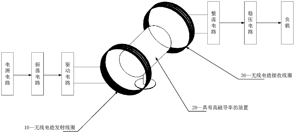
[0040] Independently build a set of magnetic coupling resonant wireless power transmission test system, including wireless power transmitting device and wireless power receiving device. The wireless energy transmitting device includes a power supply circuit, an oscillating circuit, a driving circuit and a transmitting coil; the wireless energy receiving device includes a receiving coil, a rectifying circuit, and a voltage stabilizing circuit. In this experimental system, the wireless energy transmitting and receiving coupling coils are made of Litz wire with a diameter of 1mm and 5 turns, the inductance is about 17uH, and the operating frequency of the system is 100kHz.

[0041] Keep the distance between the wireless energy transmitting coil and the wireless energy receiving coil D = 10cm, input direct current U 1 =15V, the receiver outputs DC current I 2 =0.5A, load R L =20Ω: when the transmission medium is air, the system transmission efficiency is about 40.35%; after addi...

Embodiment 2

[0042] Preferred embodiment 2: It is the same set of experimental system as preferred embodiment 1.

[0043] Input DC U 1 =15V, the receiver outputs DC current I 2 =0.5A, load R L When =20Ω, the transmission efficiency of the control experiment system remains unchanged about η=40%: when the transmission medium is air, the distance between the wireless energy transmitting coil and the wireless energy receiving coil is about 10cm; After the ferrite magnetic ring is added between the coils, the distance between the wireless energy transmitting coil and the wireless energy receiving coil is about 12cm, and the system transmission distance is increased by about 2cm.


PUM


Abstract

The application provides a magnetic coupling type wireless charging system, including a wireless electric energy transmission device which includes a power circuit, an oscillation circuit, a driving circuit and a transmitting coil; a wireless electric energy receiving device which includes a receiving coil, a rectifying circuit and a voltage stabilizing circuit, the wireless electric energy receiving device and the wireless electric energy transmitting device being coupled to each other; and a high-magnetic permeability device arranged between the wireless electric energy transmission device and the wireless electric energy receiving device, the high-magnetic permeability device including a non-metallic material having high magnetic permeability. Therefore, the magnetic coupling type wireless charging system provided by the embodiment of the application can improve the magnetic permeability between coils, thereby improving the transmission efficiency of the system.

Description

technical field [0001] The present application relates to the field of wireless charging, and more specifically, relates to a magnetic coupling wireless charging system. Background technique [0002] In a high-power wireless power transmission system such as an electric vehicle wireless power transmission system, the current between the transmitting and receiving coils can reach hundreds of amperes, generating a magnetic flux of up to hundreds of thousands of Gauss. Assuming that there is 0.1% magnetic flux leakage in the main magnetic flux, the magnetic flux leakage can also reach hundreds of milligauss, which is several times larger than the flux value specified by the International Non-Ionizing Radiation Commission standard. [0003] Magnetic coupling wireless charging technology is the mainstream technology of wireless charging at present. Reducing magnetic field leakage is the most effective way to improve the efficiency of magnetic coupling wireless charging. In the ex...

Claims


Application Information

Patent Timeline
Patent Type & Authority Applications(China)
IPC IPC(8): H02J7/00H02J50/12H01F38/14H01F27/28
CPCH01F27/2823H01F38/14H02J7/025H02J50/12
Inventor 钱平吴小卫鲁国庆
Owner SHANGHAI INST OF TECH
Why Eureka
Try Eureka