System for contaminated soil in-situ repairing and application method thereof
A technology for contaminated soil and in-situ remediation, which is applied in the field of in-situ remediation of contaminated soil systems, can solve problems affecting the popularization and application of shaft leaching technology, and reduce leaching efficiency, and is conducive to the implementation of leaching in a large area and improving the extraction efficiency. Suction efficiency, the effect that is conducive to popularization and application
- Summary
- Abstract
- Description
- Claims
- Application Information
AI Technical Summary
Problems solved by technology
Method used
Image
Examples
Embodiment 1
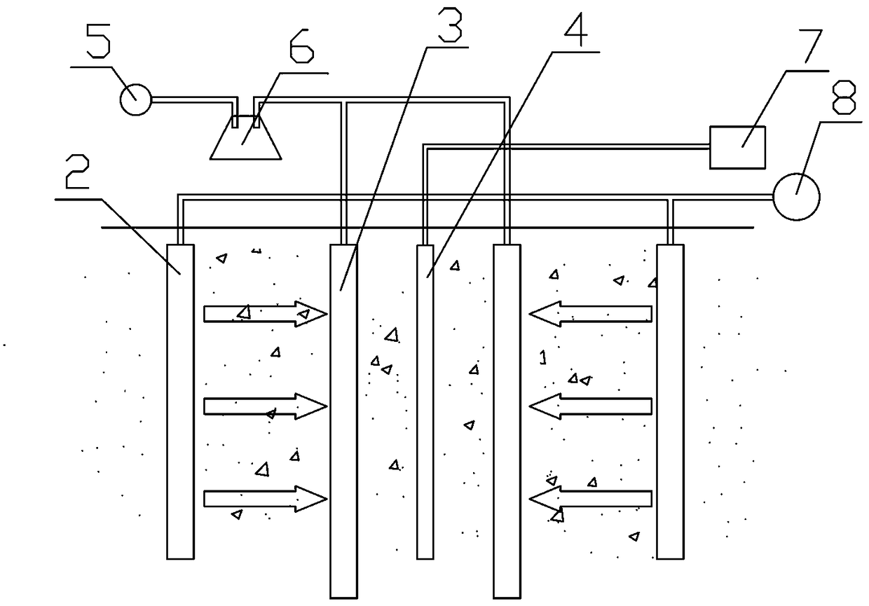
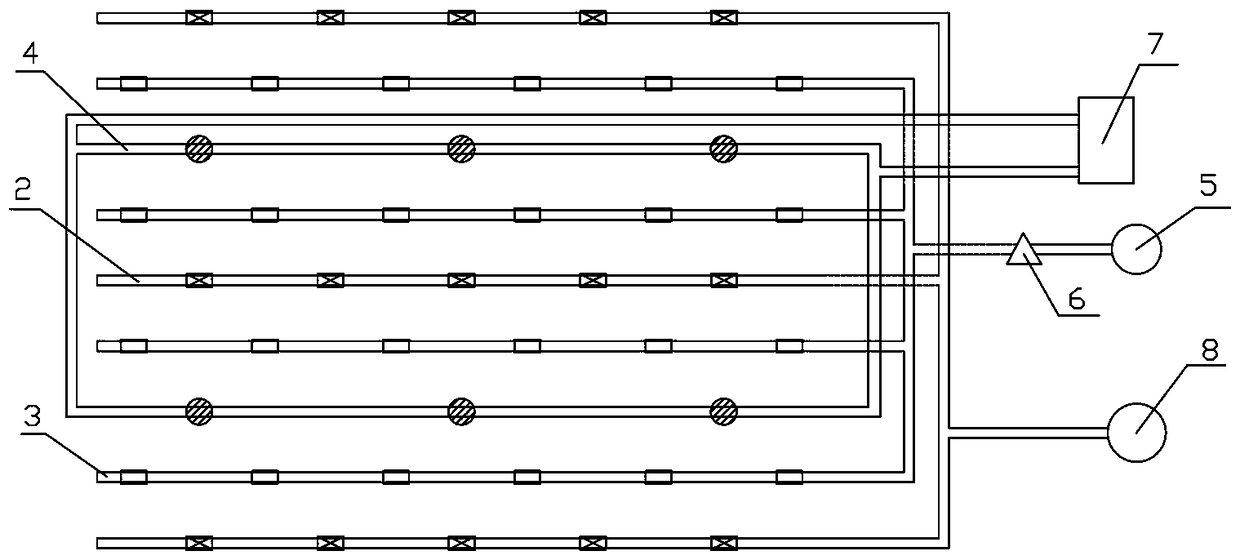
[0033] Such as figure 2 , Figure 4 , Figure 5 Shown: a system for in-situ remediation of contaminated soil, including a freezer 7, a liquid injection pump 8, a vacuum pump 5, a steam-water separator 6, several temperature sensors and a freeze-thaw rinsing unit, a freeze-thaw leaching unit The washing unit includes two liquid injection drainage plates 2, two liquid extraction drainage plates 3 and a freezing pipe 4, and the two liquid extraction drainage plates 3 are symmetrically arranged on the outside of the freezing pipe 4 with the freezing pipe 4 as the center. The liquid injection and drainage plate 2 described above is symmetrically arranged on the outside of the liquid suction and drainage plate 3 with the freezing pipe 4 as the center, and the temperature sensors are arranged at equal intervals between the freezing pipe 4 and the liquid injection and drainage plate 2; the refrigerator 7 passes through the pipeline Connected to the freezing tube 4, the freezing tub...
Embodiment 2
[0042] Such as Figure 2 to Figure 4 As shown, a system for in-situ remediation of contaminated soil includes a freezer 7, a liquid injection pump 8, a vacuum pump 5, a steam-water separator 6, several temperature sensors and two freeze-thaw rinsing units, one freeze-thaw The rinsing unit includes two liquid injection drainage plates 2, two liquid suction drainage plates 3 and a freezing pipe 4, and the two liquid suction drainage plates 3 are symmetrically arranged on the outside of the freezing pipe 4 with the freezing pipe 4 as the center. The liquid injection drainage plate 2 is symmetrically arranged on the outside of the liquid suction drainage plate 3 with the freezing pipe 4 as the center, and the temperature sensors are arranged at equal intervals between the freezing pipe 4 and the liquid injection drainage plate 2; The units are arranged in series, and the two freeze-thaw rinsing units in series share a liquid injection and drainage plate 2. The refrigerator 7 is co...
PUM
 Abstract
Description
Claims
Application Information
 - R&D
- Intellectual Property
- Life Sciences
- Materials
- Tech Scout
- Unparalleled Data Quality
- Higher Quality Content
- 60% Fewer Hallucinations
Browse by: Latest US Patents, China's latest patents, Technical Efficacy Thesaurus, Application Domain, Technology Topic, Popular Technical Reports.
© 2025 PatSnap. All rights reserved.Legal|Privacy policy|Modern Slavery Act Transparency Statement|Sitemap|About US| Contact US: help@patsnap.com


