Clamping device for processing automobile parts

A clamping device and auto parts technology, which is applied in the field of auto parts processing, can solve problems such as increased labor intensity and inability to automatically adjust

Active Publication Date: 2018-09-14
宁波隆锐机械制造有限公司
View PDF6 Cites 15 Cited by
  • Summary
  • Abstract
  • Description
  • Claims
  • Application Information

AI Technical Summary

Problems solved by technology

However, the existing part clamping device cannot be automatically adjusted according to the pipe parts and column parts of different diameters, and the distance between the clamping plates of the clamping parts needs to be adjusted manually, because the spring force between the two clamping plates is relatively large , so it is not easy to make the relative sliding between the two clamping plates, so as to manually adjust the distance between the clamping plates, the labor intensity increases

Method used


Image

  • Clamping device for processing automobile parts

Examples


Embodiment Construction

[0012] The following is further described in detail through specific implementation methods:

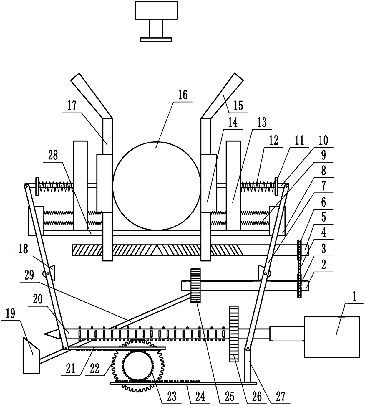
[0013] The reference signs in the drawings of the description include: cylinder 1, rotating shaft 2, first sprocket 3, chain 4, two-way lead screw 5, second sprocket 6, connecting rod 7, fixed block 8, compression spring 9, clip Holding rod 10, first baffle plate 11, extension spring 12, second baffle plate 13, clamping plate 14, material guide plate 15, parts 16, detection plate 17, connecting plate 18, wedge 19, rack column 20, The first rack 21 , the third gear 22 , the second gear 23 , the second rack 24 , the first gear 25 , the fourth gear 26 , the vertical bar 27 , the clamping platform 28 , and the push rod 29 .

[0014] The embodiment is basically as attached figure 1 Shown: a clamping device for auto parts processing, including a frame, a clamping table 28 is arranged on the frame, and a rotating shaft 2 and a bidirectional lead screw 5 that can drive the rotating shaft 2 ...


PUM


Abstract

The invention relates to a clamping device for processing automobile parts, comprising a rack and a clamping table. The clamping table is provided with a rotating shaft and a two-way screw. The rotating shaft is slidably connected with a first gear, a rack bar and a second gear and a third gear are arranged under the clamping table, the third gear is fixedly connected with the second gear, the second gear is meshed with a first rack and a second rack, the rack bar is connected with a fourth gear and the rack bar is provided with a meshing tooth set of different pitches. One end of the rack baris a tip end, the outer side of the tip end of the rack bar is slidably connected with a wedge, the upper part of the clamping table is provided with two clamping rods slidably connected with the rack, the clamping rods are both fixedly connected with two clamping plates, and the two clamping rods are both provided with elastic mechanisms for releasing the clamping plates. The clamping rods, thefirst rack and the second rack are connected through connecting rods. A detecting mechanism for rotating the two-way screw according to the diameter of the parts is arranged above the clamping table.The solution realizes automatic clamping of the parts with different diameters.

Description

technical field [0001] The invention relates to the technical field of auto parts processing, in particular to a clamping device for auto parts processing. Background technique [0002] When processing auto parts, it is necessary to clamp the auto parts. For example, when cutting and grinding the pipe parts and column parts of the automobile, it is necessary to clamp the pipe parts and column parts, so that the pipe Parts or column parts are processed more accurately. However, the existing part clamping device cannot be automatically adjusted according to the pipe parts and column parts of different diameters, and the distance between the clamping plates of the clamping parts needs to be adjusted manually, because the spring force between the two clamping plates is relatively large , so it is not easy to make the relative sliding between the two clamping plates, thereby manually adjusting the distance between the clamping plates, the labor intensity is increased. Contents...

Claims


Application Information

Patent Timeline
Patent Type & Authority Applications(China)
IPC IPC(8): B23Q3/06B23Q3/08B25B5/12B25B5/14B23Q17/20
CPCB23Q3/064B23Q3/066B23Q3/08B23Q17/20B23Q2703/04B25B5/122B25B5/127B25B5/147
Inventor 卢文斌
Owner 宁波隆锐机械制造有限公司
Why Eureka
Try Eureka