Steel plate energy-consuming composite combined column capable of bearing primary and secondary force and installation method

A composite and combined column technology, applied in the direction of columns, pillars, pier columns, etc., can solve the problems of insufficient integrity of steel tube concrete composite columns, achieve the effects of improving self-recovery performance, reducing section size, and improving seismic performance

Active Publication Date: 2018-09-14
QINGDAO TECHNOLOGICAL UNIVERSITY
View PDF4 Cites 4 Cited by
  • Summary
  • Abstract
  • Description
  • Claims
  • Application Information

AI Technical Summary

Problems solved by technology

[0003] The main purpose of the present invention is to provide a steel plate energy-dissipating composite composite column capable of primary and secondary stress and its installation method, to solve the problem of insufficient integrity of the steel tube concrete composite column in the prior art when large earthquakes occur, and to achieve primary and secondary stress. Step-by-step energy consumption and improving post-earthquake recovery ability

Method used


Image

  • Steel plate energy-consuming composite combined column capable of bearing primary and secondary force and installation method
  • Steel plate energy-consuming composite combined column capable of bearing primary and secondary force and installation method
  • Steel plate energy-consuming composite combined column capable of bearing primary and secondary force and installation method

Examples


Embodiment 1

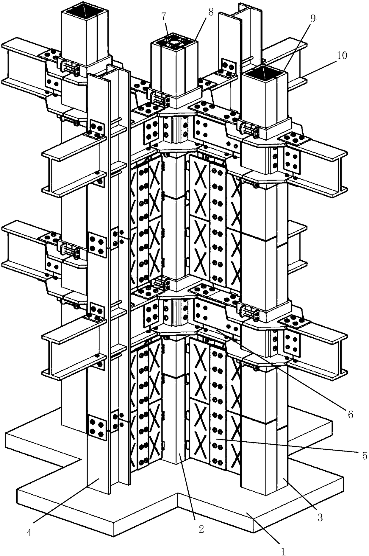
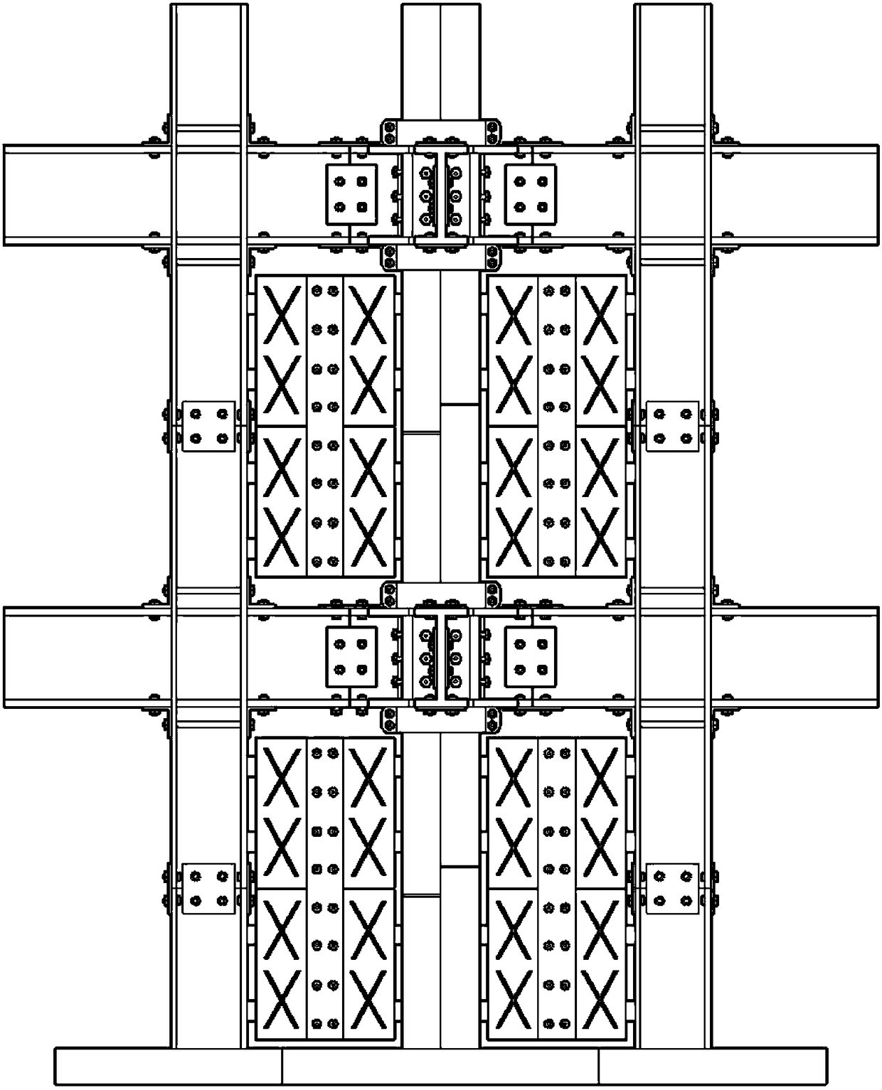
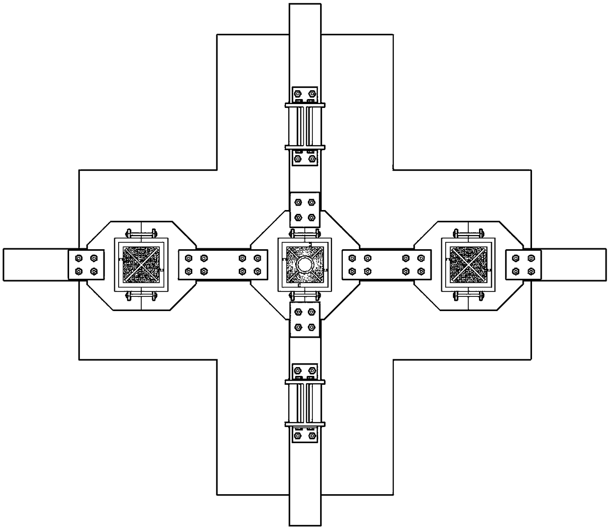
[0048] Such as Figure 1 to Figure 3 As shown, the structure of the present invention mainly includes an independent foundation 1, an A-type column 2, a B-type column 3, a C-type column 4, a hinged energy-consuming connecting member 5, and an interlayer connecting platform 6. Type A pillar 2, Type B pillar 3, and Type C pillar 4 are all vertically fixed on the independent foundation 1. The present invention adopts different columns in different directions, adopts type B columns 3 with strong shear resistance ability in the main force direction, and adopts type C columns 4 in the secondary force direction, which not only realizes the primary and secondary force, but also greatly The cross-sectional size of the composite column is reduced to a great extent, while sharing the vertical load of the structure, the structure layout is more flexible, and the combination of load bearing and space saving is realized, and the construction space and construction cost are fully saved.

[0049...

Embodiment 2

[0060] The square steel pipe of the present invention has various combinations. As shown in Figure 6(a) and Figure 6(b), whether it is A-shaped square steel pipe or B-shaped square steel pipe, it can be spliced ​​in the form of composite members.

[0061] For example, in Figure 6(a), the square steel pipe is formed by successively splicing four square steel pipe composite members, and the shape of each square steel pipe composite member is an "L-shaped" structure. In order to avoid obstructing the fixing of other bolts on the central axis, the splicing position between the square steel tube composite members is not on the central axis of the square tube, but slightly to one side.

[0062] For example, in Figure 6(b), the square steel pipe is formed by successively splicing two square steel pipe composite members, and the shape of each square steel pipe composite member is a "gate-shaped" structure. In order to avoid obstructing the fixing of other bolts on the central axis, the sp...

Embodiment 3

[0064] Such as Figure 12 to Figure 13 As shown, there are also ways to form a side column combined column for the combination of Type A column 2, Type B column 3, and Type C column 4. To form a side column combined column, the present invention can still use the B-type column 3 with strong shear resistance in the main force direction and the C-type column 4 in the secondary force direction, which not only realizes the primary and secondary force, but also greatly This reduces the cross-sectional size of the composite column, makes the structure layout more flexible while sharing the vertical load of the structure, realizes the combination of load bearing and space saving, and fully saves building space and construction costs.


PUM


Abstract

The invention relates to the technical field of structural engineering, in particular to a steel plate energy-consuming composite combined column capable of bearing primary and secondary force and aninstallation method. The steel plate energy-consuming composite combined column comprises an A-type column, B-type columns, C-type columns, hinged energy-consuming connecting members and interlayer connecting bearing platforms. Square steel tubes of the A-type column and the B-type columns are formed by splicing mortise and tenon joint structures; the A-type column is combined with the B-type columns and the C-type columns by the hinged energy-consuming connecting members; the interlayers of the A-type column, the B-type columns and the C-type columns are combined by the interlayer connectingbearing platforms; and clamping grooves of hinge shafts are formed in the outer walls of the A-type column and the B-type columns and the middle parts of the flanges of the C-type columns. The hingedenergy-consuming connecting members are connected with the two types of columns outside a plane between the columns through the hinge shafts and are rotated into the plane with the hinge shafts as rotating shafts, and energy-consuming hinge plates are connected through fixed connecting plates and high-strength bolts; and fiber concrete is poured into the gaps of the A-type column and poured into the B-type columns. The bearing of primary and secondary force is realized, and energy consumption by primary and secondary force step by step and improvement of post-earthquake recovery capability arerealized.

Description

Technical field [0001] The present invention relates to the technical field of structural engineering, in particular to a steel plate energy-consuming composite composite column capable of being subjected to primary and secondary forces and an installation method Background technique [0002] In order to withstand earthquake disasters, improving the seismic resistance of building structures is one of the main strategies. Traditional seismic design mainly relies on the seismic performance of the structure itself to resist the effects of earthquakes. This seismic method lacks self-adjustment ability and may not meet safety requirements. In addition, the excessive size of structural components not only makes the structural layout and construction inflexible, but also makes the economic investment too large. In high-rise, large-span buildings, the columns bear high axial forces, and the design of the building’s load-bearing columns is the key to ensuring that the building will work n...

Claims


Application Information

Patent Timeline
IPC IPC(8): E04C3/32E04B1/98E04H9/02
CPCE04C3/32E04H9/021E04H9/024
Inventor 牟犇王君昌王清华李培旭宣嘉琪
Owner QINGDAO TECHNOLOGICAL UNIVERSITY
Why Eureka
Try Eureka