Engine balance system

A technology of balancing system and engine, applied in the direction of machine/engine, mechanical equipment, inertia force compensation, etc., can solve the problems that affect the strength of the associated components, the operator's experience, the lack of elimination of vibration, the strong vibration of the engine, etc., and achieve ingenious structural design. , The effect of improving the service life and reducing the external size

Pending Publication Date: 2018-09-14
CHONGQING ZONGSHEN GENERAL POWER MACHINE
View PDF7 Cites 9 Cited by
  • Summary
  • Abstract
  • Description
  • Claims
  • Application Information

AI Technical Summary

Problems solved by technology

[0006] The balance device or balance system in the above two patents can balance the first-order inertial force under certain conditions, but there are also second-order and higher-order inertial forces in the engine vibration. Although the vibration acceleration of the second-order and higher-order vibration is higher than that of the first-order vibration The acceleration has been greatly reduced, but it still causes strong vibration of the engine, and the second-order and higher-order vibration frequencies are closer to the natural frequency of the application terminal, which is easy to cause resonance of the terminal. The occurrence of resonance will greatly aggravate the vibration and affect related components. The intensity and the experience of the operator, only eliminating the first-order inertial force can no longer meet the needs of current application scenarios
[0007] At present, in the existing technology, only the scheme of how to reduce the reciprocating vibration of the piston to a certain extent is introduced, but no further scheme for completely eliminating vibration, especially the second-order and higher-order vibration is proposed.

Method used


Image

  • Engine balance system
  • Engine balance system
  • Engine balance system

Examples


Embodiment 1

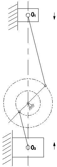
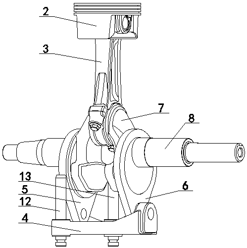
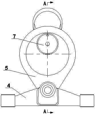
[0037] Embodiment 1: as figure 1 , 2 . As shown in 3, an engine balancing system includes an engine body member, which is characterized in that: at least two crank slider mechanisms are arranged in the engine body member, and one of the crank slider mechanisms is connected to the other crank slider mechanism. The block mechanisms are arranged oppositely; the velocity and acceleration of the slider movement in one of the slider-crank mechanisms are similar to the velocity and acceleration characteristics of the slider movement in the other slider-crank mechanism, and the ratio is approximately constant.

[0038] Wherein, in order to make the vibration elimination effect better, the crank-slider mechanism includes a connecting rod and a crankshaft 8 with a crank 7, and the length of the connecting rod and the crank eccentricity of one of the crank-slider mechanisms are L respectively. 1 and e 1 , the connecting rod length and crank eccentricity of the other slider-crank mechan...

Embodiment 2

[0060] Embodiment 2: as Figure 7 As shown, when the engine type in the engine balance system is a two-cylinder in-line engine, the balance system is composed of a first slider crank mechanism, a second slider crank mechanism and a third slider crank mechanism. The first slider-crank mechanism includes the first cylinder crank 18 driven by the first cylinder piston 16, the first cylinder connecting rod 17 and the movement of the first cylinder piston 16. The second slider-crank mechanism includes the first cylinder crank 18 driven by the first cylinder piston 16. Second cylinder piston 19, second cylinder connecting rod 20 and the second cylinder crank 21 that drives the movement of second cylinder piston 19, the third crank slider mechanism includes counterweight 22, secondary connecting rod 23 and driving counterweight 22 movement third crank. Wherein the first slider-crank mechanism and the second slider-crank mechanism are arranged opposite to the third slider-crank mecha...


PUM


Abstract

The invention discloses an engine balance system which comprises an engine body component. The engine balance system is characterized in that at least two crank-slider mechanisms are arranged in the engine body component; one crank-slider mechanism and the other crank-slider mechanism are arranged face to face; and the velocity and the acceleration of slider movement in one crank-slider mechanismare similar to the velocity and the acceleration of slider movement in the other crank-slider mechanism. The engine balance system provided by the invention has the advantages of ingenious structure design, reliability in use, and low cost; by adopting the engine balance system, first-order, second-order and high-order vibration produced during an engine operating process can be effectively eliminated, the equipment damage rate is reduced, and the experience feeling of a user is improved; and meanwhile, by adopting an arrangement form of a guide pillar mechanism and a slave connecting rod, notonly is a structure basis provided for eliminating second-order and high-order vibration, but also the problem that an engine tank occupies space is further solved, the boundary dimension of an engine is reduced, and in addition, the service life of the engine is further improved.

Description

technical field [0001] The invention relates to an engine, in particular to an engine balancing system. Background technique [0002] At present, in reciprocating mechanisms, especially in engines, the main cause of engine vibration is that the force generated by the reciprocating motion of the piston cannot be completely balanced; during each rotation of the crankshaft, the piston starts and stops twice, making the piston The reaction force of the acceleration and deceleration force is transmitted to the engine body through the crankshaft, causing the engine to generate periodic vibration. With the continuous increase of engine power demand, the piston weight and piston speed increase, and the vibration amplitude becomes larger and larger. This vibration is transmitted to the operator through the terminal equipment connected to the body, causing the operator to feel uncomfortable or unacceptable. Especially in the field of driving equipment with high comfort requirements, ...

Claims


Application Information

Patent Timeline
Patent Type & Authority Applications(China)
IPC IPC(8): F02B75/32F16F15/24
CPCF02B75/32F16F15/24
Inventor 赵吉文王义超马云刚胡樊
Owner CHONGQING ZONGSHEN GENERAL POWER MACHINE
Why Eureka
Try Eureka