Supercritical air energy storage system of heat pump

A supercritical air and energy storage system technology, applied in the field of air energy storage systems and energy storage systems, can solve the problems of low cycle efficiency and poor flexibility, and achieve the effects of high energy density, strong flexibility and high efficiency

Pending Publication Date: 2018-09-14
INST OF ENGINEERING THERMOPHYSICS - CHINESE ACAD OF SCI
View PDF0 Cites 15 Cited by
  • Summary
  • Abstract
  • Description
  • Claims
  • Application Information

AI Technical Summary

Problems solved by technology

However, the liquid air energy storage system has problems

Method used


Image

  • Supercritical air energy storage system of heat pump
  • Supercritical air energy storage system of heat pump
  • Supercritical air energy storage system of heat pump

Examples


Embodiment 1

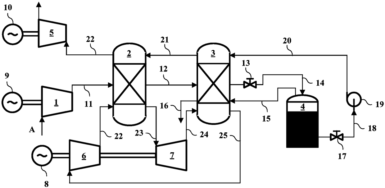
[0048] Such as figure 1 Shown is Embodiment 1 of the heat pump supercritical air energy storage system of the present invention. The heat pump supercritical air energy storage system of the present invention includes an air compressor unit 1, a heat storage heat exchanger 2, a cold storage heat exchanger 3, a liquid air storage tank 4, an air expansion unit 5, a heat pump cycle compressor unit 6, and a heat pump cycle expansion unit Unit 7, cryopump 19.

[0049] The air outlet of the heat pump cycle compressor unit 6 communicates with the air inlet of the heat pump cycle expansion unit 7 through the heat storage heat exchanger 2, and the air outlet of the heat pump cycle expansion unit 7 communicates with the air intake of the heat pump cycle compressor unit 6 through the cold storage heat exchanger 3 The heat pump cycle compressor unit 6, the heat storage heat exchanger 2, the heat pump cycle expansion unit 7, and the cold storage heat exchanger 3 form a closed heat pump coo...

Embodiment 2

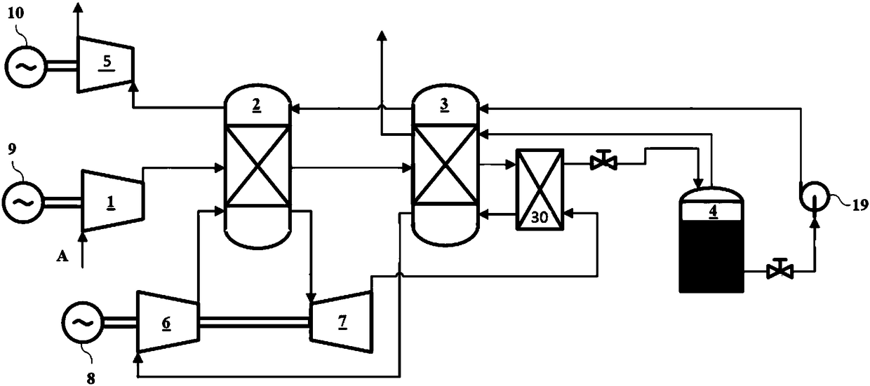
[0060] figure 2 It is Embodiment 2 of the heat pump supercritical air energy storage system of the present invention, and its main structure is the same as Embodiment 1, except that a low-temperature heat exchanger 30 is added to the heat pump refrigeration and heating circuit and the energy storage air circuit, The low-temperature heat exchanger 30 is mainly used for heat exchange between the energy storage air circuit and the heat pump refrigeration and heating circuit. The air outlet of the heat pump cycle expansion unit 7 passes through the cold side of the low-temperature heat exchanger 30, the cold storage heat exchanger 3 and then circulates with the heat pump. The air inlet of the compressor unit 6 is connected, and the air outlet of the air compressor unit 1 passes through the heat storage heat exchanger 2, the cold storage heat exchanger 3, and the hot side of the low temperature heat exchanger 30 successively, and connects with the liquid air at the top of the liqui...

Embodiment 3

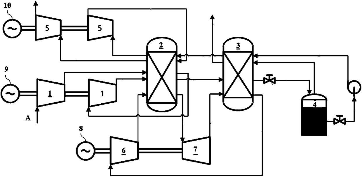
[0063] image 3 It is embodiment 3 of the heat pump supercritical air energy storage system of the present invention, its main structure is the same as that of embodiment 1, the air compressor unit 1 and the air expansion unit 5 are multi-stage in series, and the inter-stage is carried out through the heat storage heat exchanger 3 The form of heat storage and heat release.


PUM


Abstract

The invention discloses a supercritical air energy storage system of a heat pump and belongs to the technical field of energy storage. Off-peak electricity (lowelectricity ) of a power station is adopted to condense air into a high pressure state, stored cold energy and low temperature cold energy obtained by circulation of the heat pump are used for cooling the high pressure air at the low temperature state and storing thermal energy obtained by the circulation of the heat pump, and liquid air is obtained after decompression; at the peak of electricity consumption, the high pressure liquid air is condensed by a cryopump and enters a regenerator, absorbs heat,then enters in a normal temperature high pressure state and stores the cold energy, and further, absorbs stored thermal energy including air compression heat and heat pump circulation heat to drive a motor to generate electricity through an expansion machine. The supercritical air energy storage system of the heat pump has the advantages of being high energy density, high efficiency and high flexibility, being suitable forpeak regulation of power grids and various different renewable energy power stations, and free of greenhouse gases.

Description

technical field [0001] The invention belongs to the technical field of energy storage, and relates to an air energy storage system, in particular to an energy storage system based on a heat pump cycle and supercritical air to store energy and utilize the stored energy to generate electric energy. Background technique [0002] In recent years, renewable energy is gradually becoming an important source of new electricity, and major changes have taken place in the grid structure and operation mode. With the increasing popularity of renewable energy (such as wind energy, solar energy, etc.), and the urgent need for grid peak regulation, improving grid reliability, and improving power quality, the importance of power storage systems has become increasingly prominent. Energy storage is an important component and key supporting technology of smart grids, energy systems with a high proportion of renewable energy, and "Internet +" smart energy (hereinafter referred to as energy Inter...

Claims


Application Information

Patent Timeline
IPC IPC(8): F04B41/02F01K7/32F01D15/10F25J1/00F25J1/02
CPCF01D15/10F01K7/32F04B41/02F25J1/0012F25J1/0228F25J1/004F25J1/0045F25J1/005F25J1/0062F25J1/0065F25J1/0077F25J1/0204F25J1/0212F25J1/0242F25J1/0251F25J1/0288F25J1/0296F25J2205/24F25J2230/04F25J2230/30F25J2240/90Y02E60/16
Inventor 王亮林曦鹏陈海生凌浩恕陈磊
Owner INST OF ENGINEERING THERMOPHYSICS - CHINESE ACAD OF SCI
Why Eureka
Try Eureka