
Variable-quantity and variable-pressure plunger pump

A technology of variable pressure column and plunger pump, which is applied in the field of hydraulic pumps, can solve the problems that the output pressure of the plunger pump cannot be adjusted, and achieve the effects of avoiding improper processing, realizing the conversion of oil circuits, and being convenient to use

Active Publication Date: 2018-09-14
HANGZHOU OUDUN ELECTROMECHANICAL
View PDF6 Cites 4 Cited by
  • Summary
  • Abstract
  • Description
  • Claims
  • Application Information

AI Technical Summary

Problems solved by technology

[0005] In order to overcome the problem that the output pressure of the existing plunger pump cannot be adjusted, the present invention provides a variable pressure variable plunger pump

Method used


Image

  • Variable-quantity and variable-pressure plunger pump
  • Variable-quantity and variable-pressure plunger pump
  • Variable-quantity and variable-pressure plunger pump

Examples


Embodiment 1

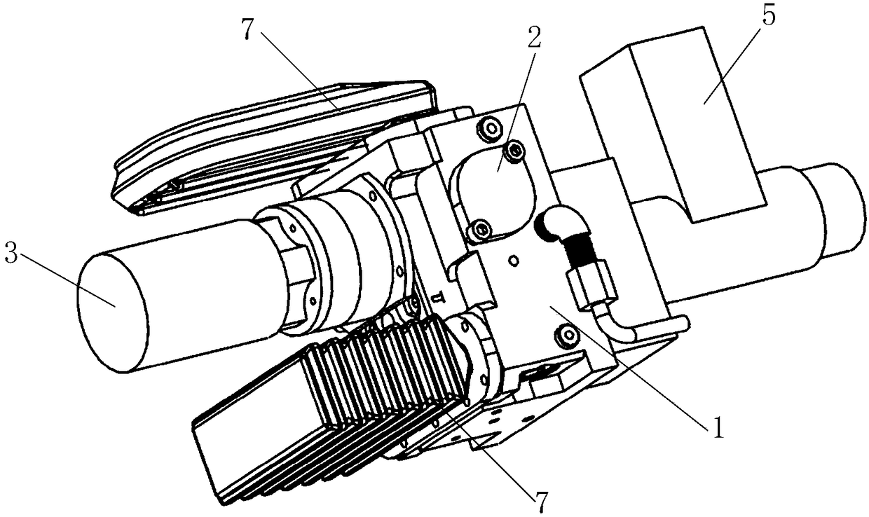
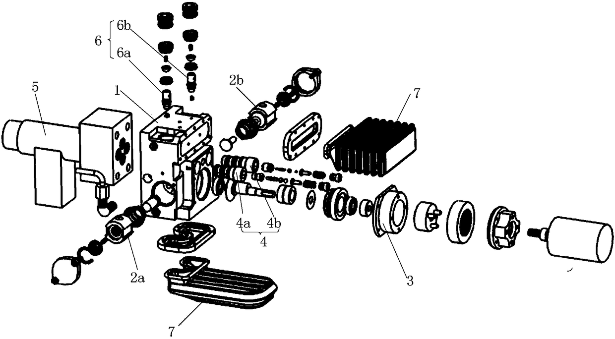
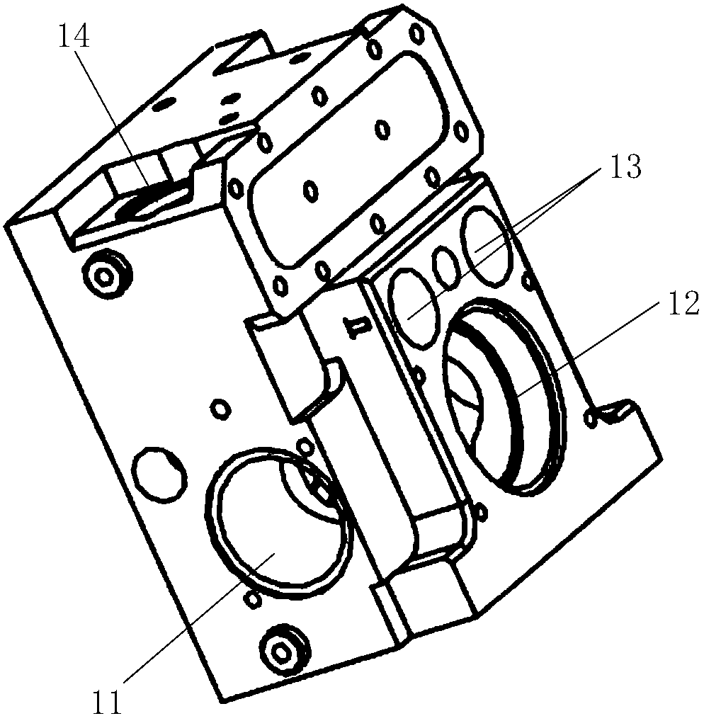
[0034] Such as Figure 1 to Figure 3C As shown, the variable pressure variable plunger pump provided in this embodiment includes a pump body 1 , a plunger assembly 2 , a power assembly 3 , an oil pressure adjustment assembly 4 and an oil pressure output assembly 5 . The plunger assembly 2 is arranged on the pump body 1 . The power assembly 3 is arranged on the pump body 1 and is connected to the plunger assembly 2 to drive the plunger assembly 2 to pump out the oil entering the pump body 1 . The oil pressure adjustment assembly 4 is installed in the pump body 1. The oil pumped by the plunger assembly 2 is output after passing through the oil pressure adjustment assembly 4. When the oil pressure exceeds the set value, the oil pressure adjustment assembly 4 releases the pressure , reduce the output oil pressure. The oil pressure output assembly 5 is arranged on the pump body 1 and communicates with the oil pressure adjustment assembly 4, the oil return passage on the pump body...

Embodiment 2

[0053] This embodiment is basically the same as Embodiment 1 and its variations, the difference is that in this embodiment the oil pressure output assembly is a two-position four-way electromagnetic control directional valve, which is in the two-position three-way electromagnetic control directional valve of the first embodiment. An additional valve 58 is added on the basis, and there are two steel balls 56a, 56b in the main valve body 51 of the solenoid valve.

[0054] The additional valve 58 includes a piston 581, an additional valve spool 582 and an additional valve seat 583. The piston 581 is connected to the additional valve spool 582. The additional valve seat 583 is provided with a second oil inlet and outlet port B, and the pressure oil port P is connected to the additional valve seat 583. The oil inlets of the valve 48 are connected, the oil return port T is connected to the cavity in the valve seat of the additional valve, the first oil inlet and outlet A is connected...


PUM


Abstract

The invention provides a variable-quantity and variable-pressure plunger pump. The variable-quantity and variable-pressure plunger pump comprises a pump body, a plunger assembly, a power assembly, anoil pressure adjusting assembly and an oil pressure output assembly. The plunger assembly is arranged on the pump body. The power assembly is arranged on the pump body and connected with the plunger assembly, and drives the plunger assembly to move to pump out oil fed in the pump body. The oil pressure adjusting assembly is arranged on the pump body; the oil pumped out by the plunger assembly is output after passing through the oil pressure adjusting assembly; and when the oil pressure exceeds a set value, the oil pressure adjusting assembly relieves the pressure to reduce the output oil pressure. The oil pressure output assembly is arranged on the pump body, respectively communicates with the oil pressure adjusting assembly, the pump body and an external execution mechanism, and controlsopening, stop and flowing direction of the oil.

Description

technical field [0001] The invention relates to a hydraulic pump, and in particular to a variable pressure variable plunger pump. Background technique [0002] The plunger pump is an important hydraulic device, which is generally driven by an electric motor, and converts the mechanical energy of the motor shaft rotation into hydraulic energy. Changes to achieve oil absorption and oil pressure. For some occasions, such as fire protection and construction fields, the miniaturization of tool products also requires the plunger pump to develop in the direction of small and micro. [0003] Through market research, it is found that the output pressure of the plunger pumps currently on the market cannot be adjusted during work. In order to improve work efficiency, the actuator is required to move forward and backward at a faster speed. The faster the movement speed will inevitably require the output pressure of the plunger pump to be relatively small. When the small output pressur...

Claims


Application Information

Patent Timeline
Patent Type & Authority Applications(China)
IPC IPC(8): F04B49/08F04B49/24F04B53/10
CPCF04B49/08F04B49/24F04B53/10F04B53/1002
Inventor 毛剑峰王俊王小鹏高铭
Owner HANGZHOU OUDUN ELECTROMECHANICAL
Learn More