
Inflation valve element, explosion-proof valve capable of detecting air tightness of box body through rapid inflation and detection method
A technology for explosion-proof valves and inflation valves, which is applied in fluid tightness testing, inflation valves, safety valves, etc. It can solve the problems of poor secondary sealing of inflation holes, low detection efficiency, and slow inflation speed, etc., to avoid Poor secondary seal, high detection efficiency and fast air intake speed
- Summary
- Abstract
- Description
- Claims
- Application Information
AI Technical Summary
Problems solved by technology
Method used
Image

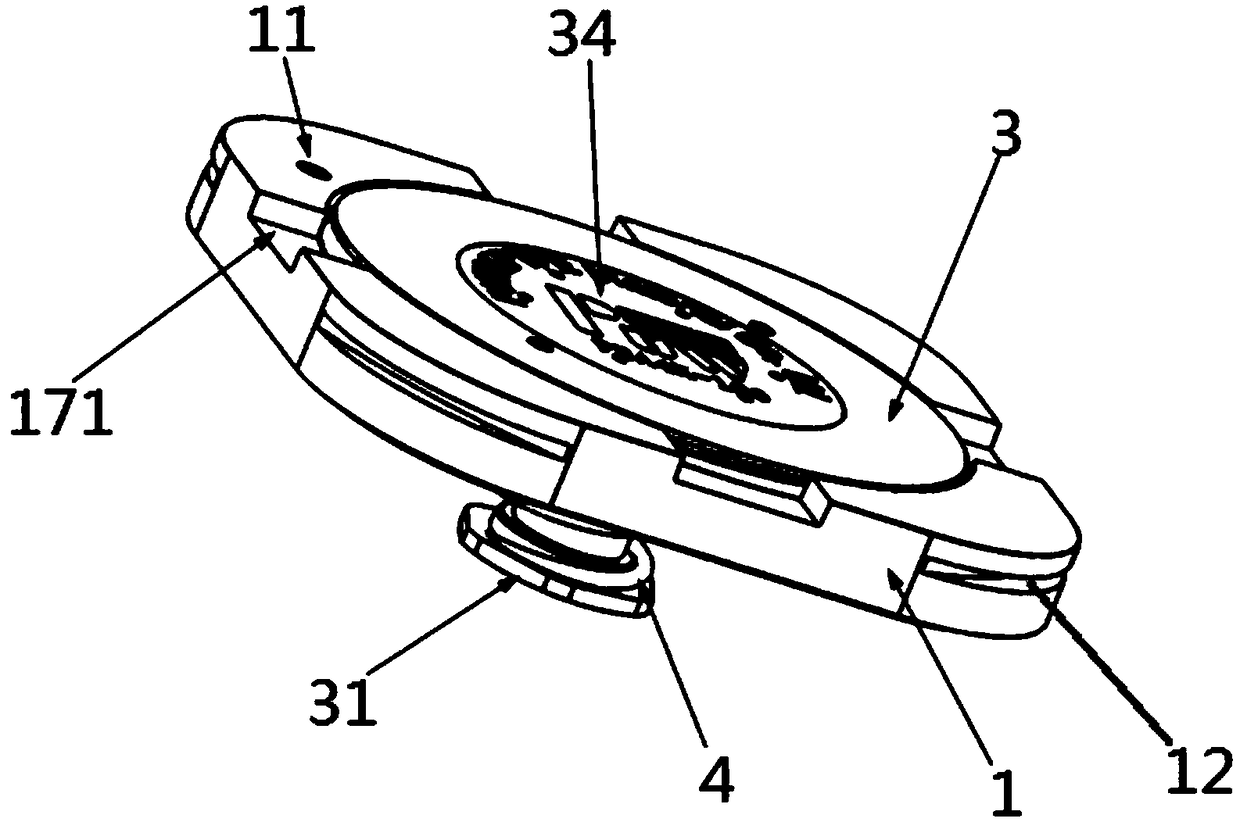
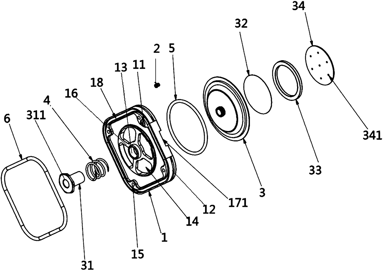
Examples
Embodiment Construction
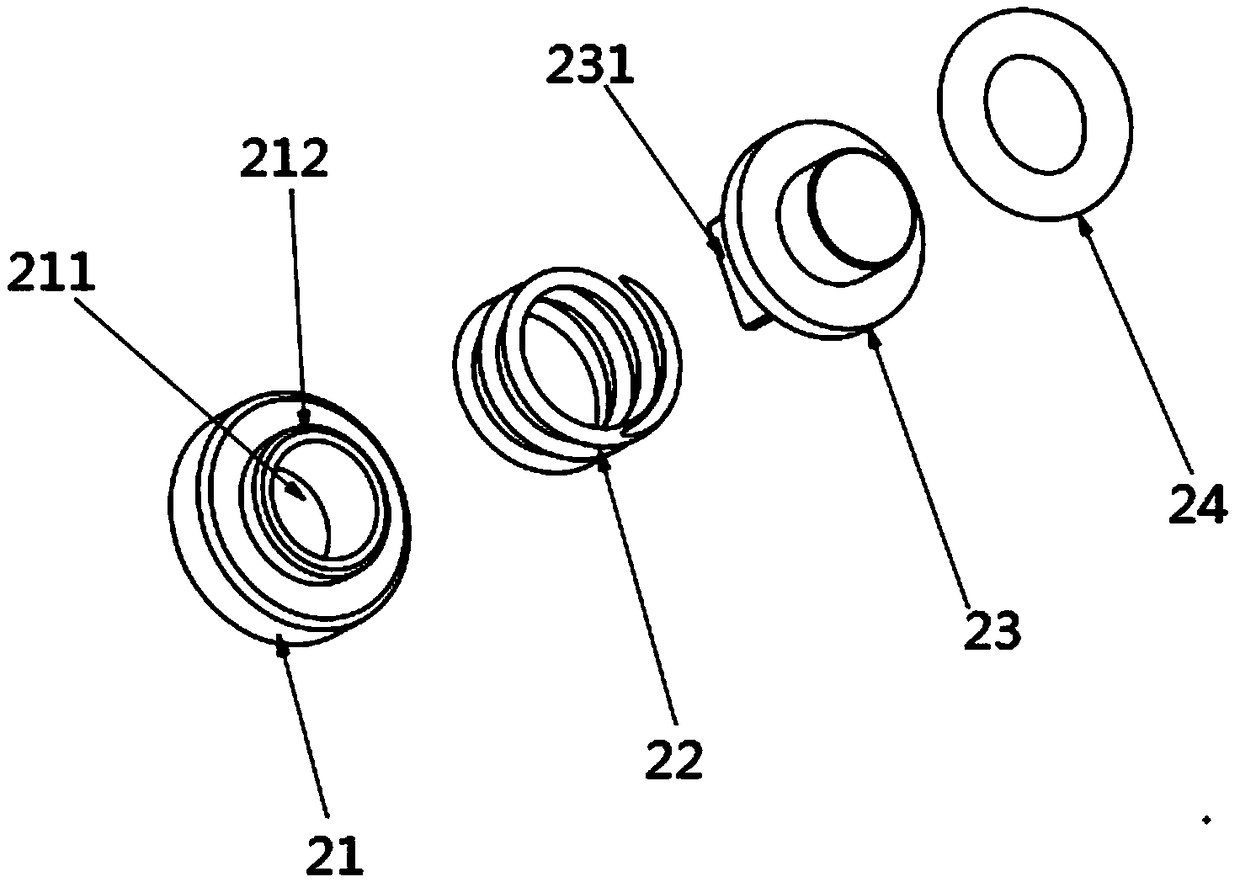
[0036] see image 3 , the invention provides an inflatable valve core, the inflatable valve core includes a fixed part 21, a compression spring 22, an inflatable piston 23, and a rubber seal 24, and one end of the inflatable piston 23 is connected to the fixed part 21 through a compressed spring 22, and the inflated The other end of the piston 23 is connected with a rubber seal 24 .
[0037] In this embodiment, one end of the inflation piston 23 is further provided with a guide post 231 , and the fixing member 21 is provided with a guide hole 211 for radially limiting the guide post 231 .
[0038] In order to prevent the inflating piston 23 from being deflected when inflated, and the seal cannot be reset after inflating, a guide column 231 is provided on the inflating piston 23, and the guiding column 231 can move up and down through the hollow fixing part 21, ensuring the accurate reset of the inflating piston 23 after inflating seal.
[0039] see Figure 1-4 , the present...
PUM
 Abstract
Description
Claims
Application Information