
A heat transfer oil circulating combustion furnace and method thereof

A technology of circulating combustion and heat conduction oil, which is applied in the field of heat conduction oil heating, to achieve the effects of preventing heat loss, simple structure, and stable fuel combustion

Active Publication Date: 2019-11-26
沈萍萍
View PDF6 Cites 0 Cited by
  • Summary
  • Abstract
  • Description
  • Claims
  • Application Information

AI Technical Summary

Problems solved by technology

[0003] Existing boilers are often fueled by solid fuels such as coal, or boilers that use gaseous fuels such as gas are now very mature, and renewable liquid fuels such as alcohol are difficult to apply to heat-conducting oil boilers.

Method used


Image

  • A heat transfer oil circulating combustion furnace and method thereof
  • A heat transfer oil circulating combustion furnace and method thereof
  • A heat transfer oil circulating combustion furnace and method thereof

Examples


Embodiment Construction

[0022] The present invention will be further described below in conjunction with the accompanying drawings.

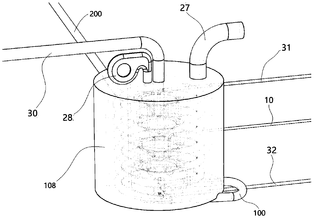
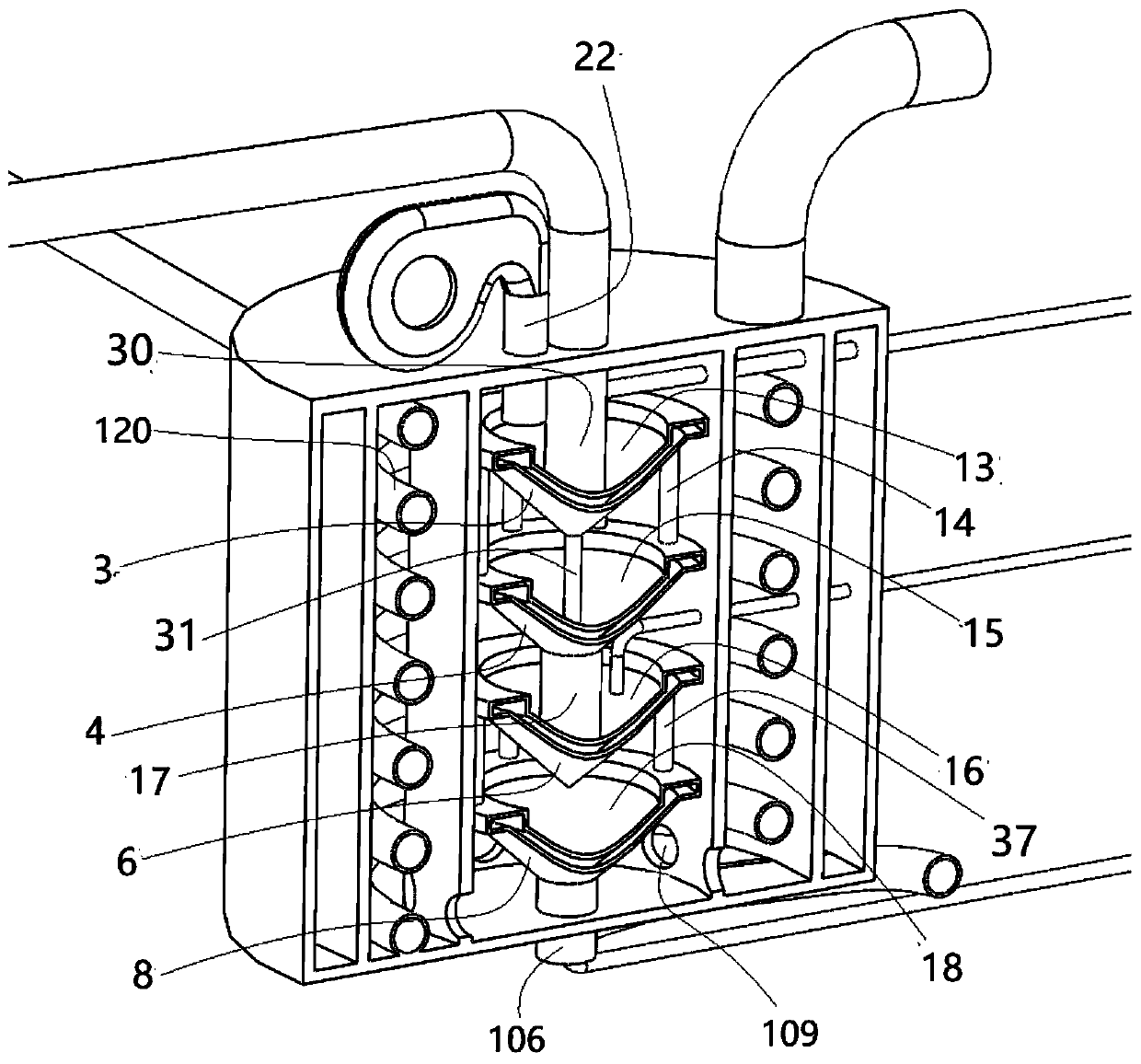
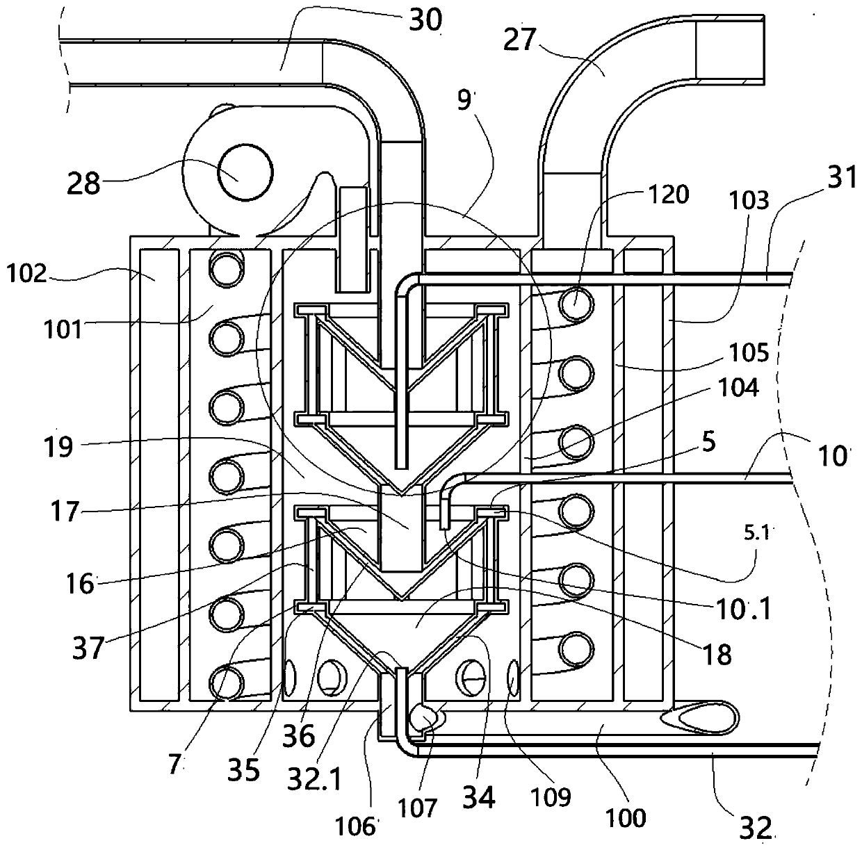
[0023] Structure introduction: attached Figures 1 to 4 The heat transfer oil circulating combustion furnace shown includes a combustion furnace body 108, the combustion furnace body 108, a cold heat transfer oil supply pipe 200 and a heat transfer oil outlet pipe 30, and the oil outlet end of the cold heat transfer oil supply pipe 200 The oil inlet end of the combustion furnace body 108 is communicated with, and the oil outlet end of the combustion furnace body 108 is connected with the oil inlet end of the heat conduction oil outlet pipe 30 .

[0024] The combustion furnace body 108 includes an outer thermal insulation shell 103, the outer thermal insulation shell 103 is a vertical cylindrical airtight shell structure, the inner cavity of the thermal insulation shell 103 is coaxially provided with a flue gas wrapping shell 105, The flue gas wrapping shell 105 is an ...


PUM


Abstract

The invention discloses a conduction oil circulating combustion furnace which comprises a combustion furnace body, a cold conduction oil supply pipeline and a hot conduction oil discharge pipe, wherein the oil outlet of the cold conduction oil supply pipeline communicates to the oil inlet of the combustion furnace body and the oil outlet of the combustion furnace body communicates to the oil inletof the hot conduction oil discharge pipe. The conduction oil circulating combustion furnace disclosed by the invention is simple in structure which is suitable for a liquid fuel. A first furnace core, a second furnace core, a third furnace core and a fourth furnace core are of hollow heat-resistant thin wall structures filled with flowing oil, so that the fuel liquids carried on the second, thirdand fourth furnace cores are free of boiling phenomena, and the fuel is combusted more stably.

Description

technical field [0001] The invention belongs to the field of heat conduction oil heating, in particular to a heat conduction oil circulating combustion furnace and a method thereof. Background technique [0002] The heat-conducting oil boiler uses heat-conducting oil as the medium, and uses the hot oil circulating oil pump to force the medium to circulate in liquid phase, transfer the heat energy to the heat-consuming equipment and then return to the heating furnace for reheating, and deliver the heat energy to the heat-consuming equipment before returning to the heating furnace for reheating , with high working temperature under low pressure, and high-precision control of medium operation; [0003] Existing boilers are often fueled by solid fuels such as coal, or boilers that use gaseous fuels such as gas are now very mature, and renewable liquid fuels such as alcohol are difficult to be well applied to heat transfer oil boilers. Contents of the invention [0004] Purpos...

Claims


Application Information

Patent Timeline
Patent Type & Authority Patents(China)
IPC IPC(8): F24H7/00F24H9/18
CPCF24H7/005F24H9/18
Inventor 张兰英
Owner 沈萍萍
Learn More