
Design method of focal length controllable negative-refraction grating plano-concave lens

A design method and negative refraction technology, applied in the direction of diffraction grating, optics, optical elements, etc., can solve the problems of material selection and structure preparation, limit the use range of focal field and focus effect, etc., achieve energy concentration, flexible regulation, wide range of materials

Inactive Publication Date: 2018-09-14
NANJING UNIV OF POSTS & TELECOMM
View PDF6 Cites 5 Cited by
  • Summary
  • Abstract
  • Description
  • Claims
  • Application Information

AI Technical Summary

Problems solved by technology

[0003] The traditional parabolic mirror makes the beam converge in the same direction by changing the phase of the wavefront, but its reflection focusing method has certain shortcomings. There is mutual influence, which limits the use range and focusing effect of the focal field. In addition, traditional lenses can only achieve ideal focusing under paraxial conditions, and there are certain requirements for the polarization state of light
One-dimensional photonic crystal plano-concave mirrors can achieve sub-wavelength focusing and are effective for any cylindrical vector light, but there are certain difficulties in the selection of materials and the preparation of structures

Method used


Image

  • Design method of focal length controllable negative-refraction grating plano-concave lens
  • Design method of focal length controllable negative-refraction grating plano-concave lens
  • Design method of focal length controllable negative-refraction grating plano-concave lens

Examples


Embodiment Construction

[0028] Objects, advantages and features of the present invention will be illustrated and explained by the following non-limiting description of preferred embodiments. These embodiments are only typical examples of applying the technical solutions of the present invention, and all technical solutions formed by adopting equivalent replacements or equivalent transformations fall within the protection scope of the present invention.

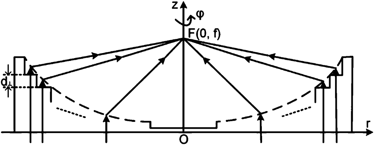
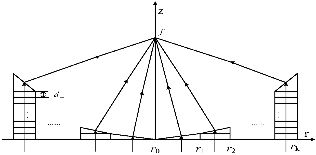
[0029] The invention discloses a design method of a negative refraction grating plano-concave mirror with controllable focal length. The negative refraction grating plano-concave mirror is a cylindrically symmetrical plano-concave lens, and its incident surface is a circular plane, and its outgoing surface is a concave surface. The central part is a small circular plane, and the height increases from the inside to the outside to form a "small circular plane" + multiple "cylindrical-toroidal" concave surfaces. The height of the cylindrical surfaces is ...


PUM

PropertyMeasurementUnit
Grating periodaaaaaaaaaa

Abstract

The invention discloses a design method of a focal length controllable negative-refraction grating plano-concave lens. The negative-refraction grating plano-concave lens is a plano-concave lens in cylindrical symmetry, an incident surface includes a circular plane, an emitting surface includes a concave surface, the central portion of the concave surface includes a small circular plane, the concave surface including one small circular plane and multiple cylindrical surfaces and annulus surfaces with height equivalent progressive increase from inside to outside is formed, and the radius of thesmall circular plane and the sizes of the annulus surfaces are determined by that S1) the light wavelength lambda0 of the negative-refraction grating plano-concave lens is determined, a proper mediumrefractive index n is selected, the height of the cylindrical surfaces is adjusted, and thus, a negative refraction grating realizes negative refraction in the working wavelength; and S2) on the premise that incident light is input vertically, an equivalent negative refraction index neff is obtained according to the working wavelength, material refractive index and the cylindrical surface height determined in the step S1). Via the method, a preset focal length can be regulated flexibly, incident light and emitting light are focused in the same side of the normal, and energy of electromagneticwaves is more concentrated.

Description

technical field [0001] The invention relates to a design method of a negative refraction grating plano-concave mirror with controllable focal length, belongs to the field of artificial microstructure materials and fine light field regulation, and can be used in the technical fields of light field focusing, particle acceleration, optical micro-control and the like. Background technique [0002] Artificial microstructure is a hotspot in the field of optics. It can achieve some effects that macrostructures do not have, such as particle acceleration, single-molecule imaging, small size effect and quantum tunneling effect. Photolithography and other fields have broad application prospects. [0003] The traditional parabolic mirror makes the beam converge in the same direction by changing the phase of the wavefront, but its reflection focusing method has certain shortcomings. There is mutual influence, which limits the use range and focusing effect of the focal field. In addition...

Claims


Application Information

Patent Timeline
IPC IPC(8): G02B27/00G02B5/18
CPCG02B5/1814G02B27/0012
Inventor 许吉刘山峰刘希文杨茜刘扬眉孙钰淇刘宁陆云清
Owner NANJING UNIV OF POSTS & TELECOMM
Learn More