
Optical imaging system and head-mounted display device

An optical imaging system and display module technology, applied in optics, optical components, instruments, etc., can solve problems such as unfavorable thinning of head-mounted devices and shrinking product size, and achieve focusing effect, thinning, and reduction. The effect of size and weight

Active Publication Date: 2021-11-02
BEIJING BOE TECH DEV CO LTD +1
View PDF7 Cites 6 Cited by
  • Summary
  • Abstract
  • Description
  • Claims
  • Application Information

AI Technical Summary

Problems solved by technology

[0003] However, most imaging systems in existing head-mounted devices use refractive optical lenses, which modulate the wavefront of light through optical path accumulation, and require a lens combination of various materials to achieve achromatic imaging of the lens, which greatly limits the product quality. The further reduction in size is not conducive to the thinning and lightening of head-mounted devices

Method used


Image

  • Optical imaging system and head-mounted display device
  • Optical imaging system and head-mounted display device
  • Optical imaging system and head-mounted display device

Examples


Embodiment Construction

[0042] Hereinafter, embodiments of the present disclosure will be described with reference to the drawings. It should be understood, however, that these descriptions are exemplary only, and are not intended to limit the scope of the present disclosure. It should be noted that the same reference numerals will be used in different drawings to refer to the same elements already described. Also, in the following description, descriptions of well-known structures and techniques are omitted to avoid unnecessarily obscuring the concept of the present disclosure.

[0043] Various structural schematic diagrams according to embodiments of the present disclosure are shown in the accompanying drawings. The figures are not drawn to scale, with certain details exaggerated and possibly omitted for clarity of presentation. The shapes of the various regions and layers shown in the figure, as well as their relative sizes and positional relationships are only exemplary, and may deviate due to ...


PUM

PropertyMeasurementUnit
lengthaaaaaaaaaa
widthaaaaaaaaaa
heightaaaaaaaaaa

Abstract

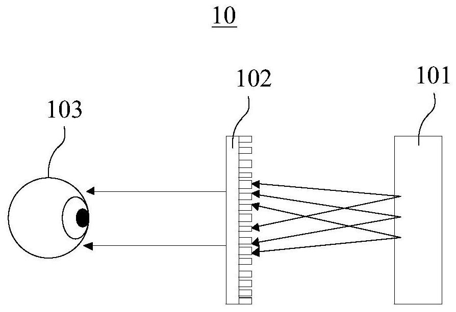
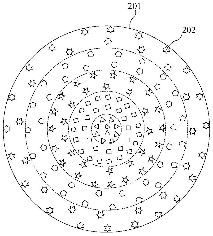
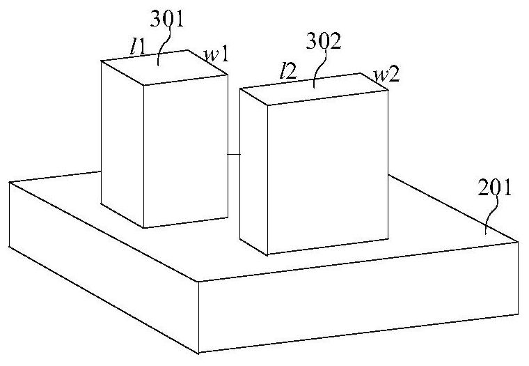
The invention discloses an optical imaging system and a head-mounted display device, wherein the optical imaging system comprises a display module and a super lens, and first linearly polarized light emitted when the display module displays a target object is collimated by the super lens and imaged on human eyes. The superlens comprises a first substrate and a plurality of superstructure units arranged on the surface of the first substrate according to a preset rotation rule, the compensation phase of each superstructure unit in a visible light wave band and the angular frequency of incident light meet a linear relation, and the compensation phase of each superstructure unit in the visible light wave band meets a linear relation from the center position to the edge position of the superlens; the slopes of the linear relations corresponding to different superstructure units are sequentially reduced. Compared with a traditional imaging system, the head-mounted display device is light and thin.

Description

technical field [0001] The invention belongs to the field of display technology, and in particular relates to an optical imaging system and a head-mounted display device. Background technique [0002] With the development of virtual reality (Virtual Reality, VR) / augmented reality (Augmented Reality, AR) technology, there are endless head-mounted products on the market. For the user's experience, achieving light and thin is an important development direction of head-mounted products. [0003] However, most imaging systems in existing head-mounted devices use refractive optical lenses, which modulate the wavefront of light through optical path accumulation, and require a lens combination of various materials to achieve achromatic imaging of the lens, which greatly limits the product quality. Further reduction in size is not conducive to realizing thinner and lighter head-mounted devices. Contents of the invention [0004] Embodiments of the present invention help to improv...

Claims


Application Information

Patent Timeline
Patent Type & Authority Applications(China)
IPC IPC(8): G02B27/01
CPCG02B27/0172G02B2027/0116G02B2027/0178
Inventor 周健
Owner BEIJING BOE TECH DEV CO LTD
Learn More