
Light shielding plate and preparation method and application thereof

A technology of shading plate and ultraviolet light, which is applied in the direction of microlithography exposure equipment and photolithography exposure equipment, etc., can solve the problems of uneven ultraviolet light irradiation energy, affecting product quality, affecting product line width uniformity, etc., and achieving production Inexpensive, fast response time, easy-to-achieve effects

Active Publication Date: 2018-09-14
SHENZHEN CHINA STAR OPTOELECTRONICS TECH CO LTD
View PDF11 Cites 1 Cited by
  • Summary
  • Abstract
  • Description
  • Claims
  • Application Information

AI Technical Summary

Problems solved by technology

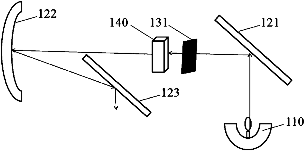
Wherein, there is a mechanical visor 131 between the fly’s eye 140 and the first reflector 121 to control whether the ultraviolet light passes through or not. The opening and closing of the mechanical visor 131 needs to be controlled by a motor, and the time required for one opening and closing is about Between 0.5s and 1s, this will cause the energy of the ultraviolet light irradiation in the same exposure range to be uneven, which will affect the uniformity of the product line width in the plane, thereby affecting the product quality

Method used


Image

  • Light shielding plate and preparation method and application thereof
  • Light shielding plate and preparation method and application thereof
  • Light shielding plate and preparation method and application thereof

Examples


Embodiment Construction

[0042] The following descriptions are preferred implementations of the embodiments of the present invention. It should be pointed out that those skilled in the art can make some improvements and modifications without departing from the principles of the embodiments of the present invention. These improvements And retouching are also regarded as the scope of protection of the embodiments of the present invention.

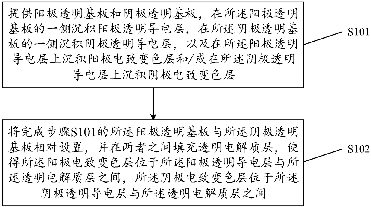
[0043] see figure 1 , the preparation method of a kind of shading plate provided for the implementation of the present invention, comprises the steps:

[0044] Step S101: providing an anode transparent substrate and a cathode transparent substrate, depositing an anode transparent conductive layer on one side of the anode transparent substrate, depositing a cathode transparent conductive layer on one side of the cathode transparent substrate, and depositing a cathode transparent conductive layer on one side of the anode transparent conductive layer An anode electroch...


PUM

PropertyMeasurementUnit
Thicknessaaaaaaaaaa
Thicknessaaaaaaaaaa

Abstract

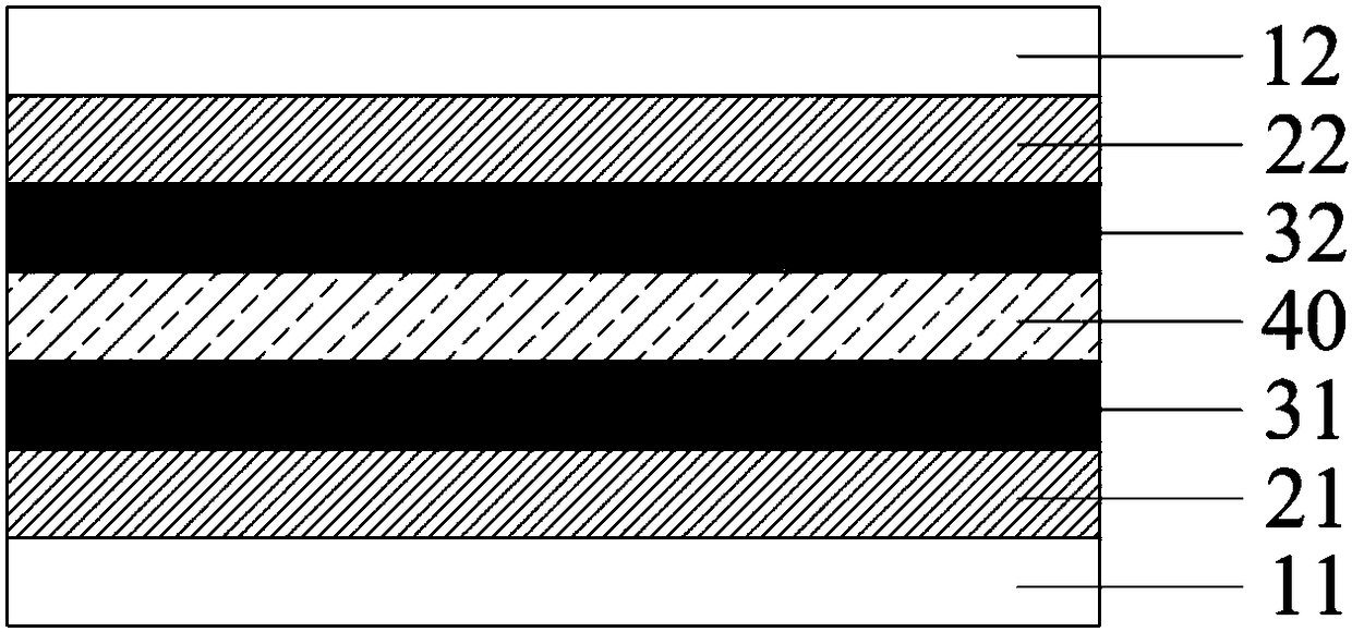
The present invention provides a light shielding plate, the light shielding plate comprises an anode transparent substrate and a cathode transparent substrate which are oppositely disposed, the lightshielding plate also comprises a transparent electrolyte layer and an electrochromic layer between the anode transparent substrate and the cathode transparent substrate, the electrochromic layer comprises an anode electrochromic layer and a cathode electrochromic layer, the anode electrochromic layer is located between the anode transparent substrate and the transparent electrolyte layer, and thecathode electrochromic layer is located between the cathode transparent substrate and the transparent electrolyte layer. The light shielding plate is provided with the anode electrochromic layer and / or the cathode electrochromic layer. The ultraviolet light transmittance can be controlled by control of the color of the light shielding plate by an electric field, the uniform ultraviolet light transmittance in a same exposure range can be ensured, precise exposure can be achieved, and product quality and exposure process stability can be improved. At the same time, compared with a traditional mechanical light shielding plate, the opening and closing time is avoided, and the response time is short. The invention also provides a preparation method and application of the light shielding plate.

Description

technical field [0001] The invention relates to the field of preparation of liquid crystal display panels, in particular to a light-shielding plate and its preparation method and application. Background technique [0002] In the preparation process of liquid crystal display (Liquid Crystal Display, LCD), the exposure machine is the key equipment for preparing fine-quality patterns, and the current proximity exposure machine is in use (such as figure 1 shown), the ultraviolet light passes through the collector mirror 110 and shoots to the first reflector 121, and then passes through the fly eye 140 to make the light uniform and parallel, and then shoots to the second reflector 122 and the third reflector 123, and passes through the mask Expose the substrate to form a pattern. Wherein, there is a mechanical visor 131 between the fly’s eye 140 and the first reflector 121 to control whether the ultraviolet light passes through or not. The opening and closing of the mechanical v...

Claims


Application Information

Patent Timeline
IPC IPC(8): G03F7/20
CPCG03F7/20
Inventor 袁夏梁
Owner SHENZHEN CHINA STAR OPTOELECTRONICS TECH CO LTD
Learn More