Optical recording medium
a recording medium and optical technology, applied in the field of optical recording mediums, can solve the problems of insufficient productivity, long-term stability and storage properties, and appropriate organic dyes that can be used, and achieve the effects of changing the transmittance or recording sensitivity in the recording layer, good recording properties, and controlling the transmittance and recording sensitivity
- Summary
- Abstract
- Description
- Claims
- Application Information
AI Technical Summary
Benefits of technology
Problems solved by technology
Method used
Image
Examples
first embodiment
1. First Embodiment
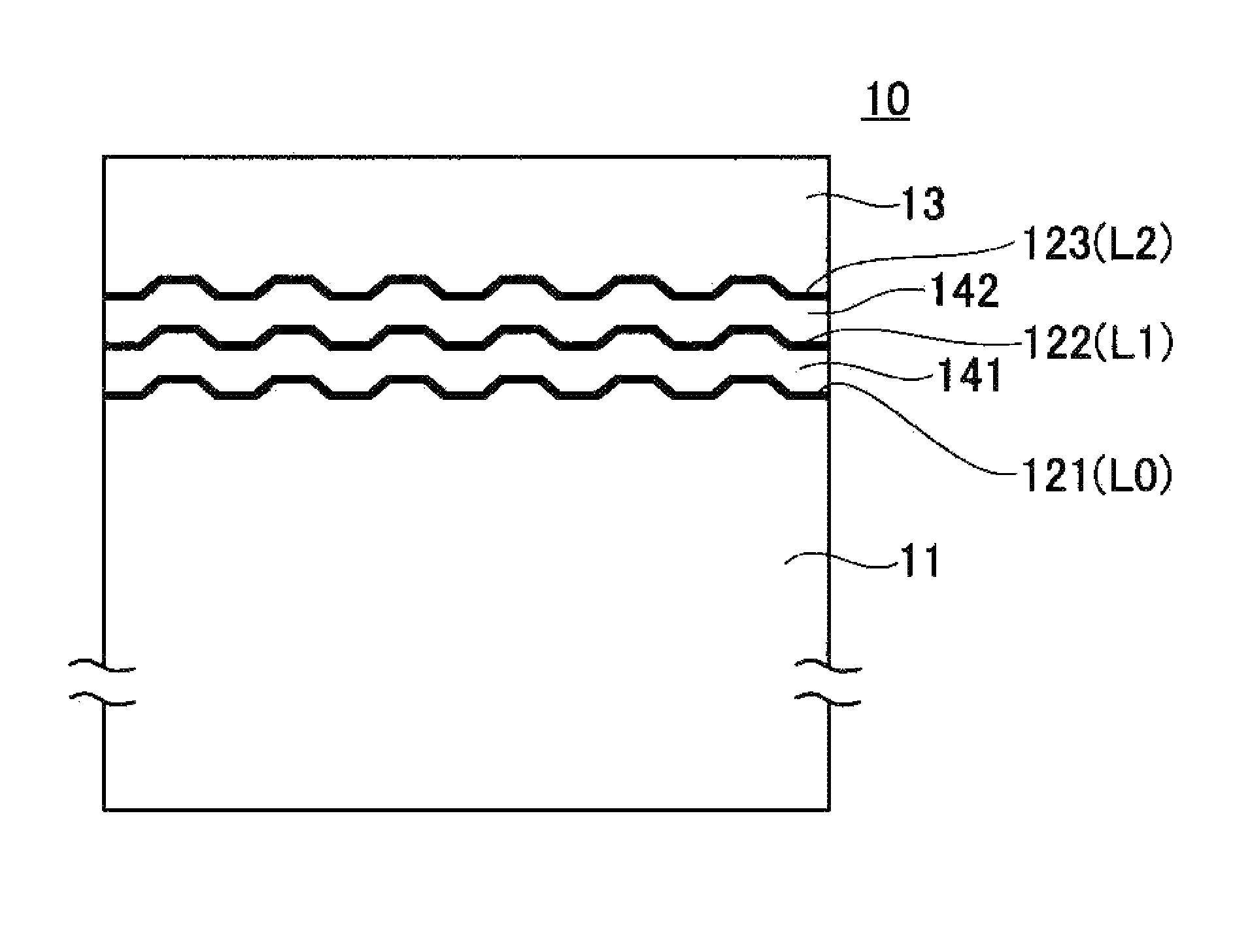
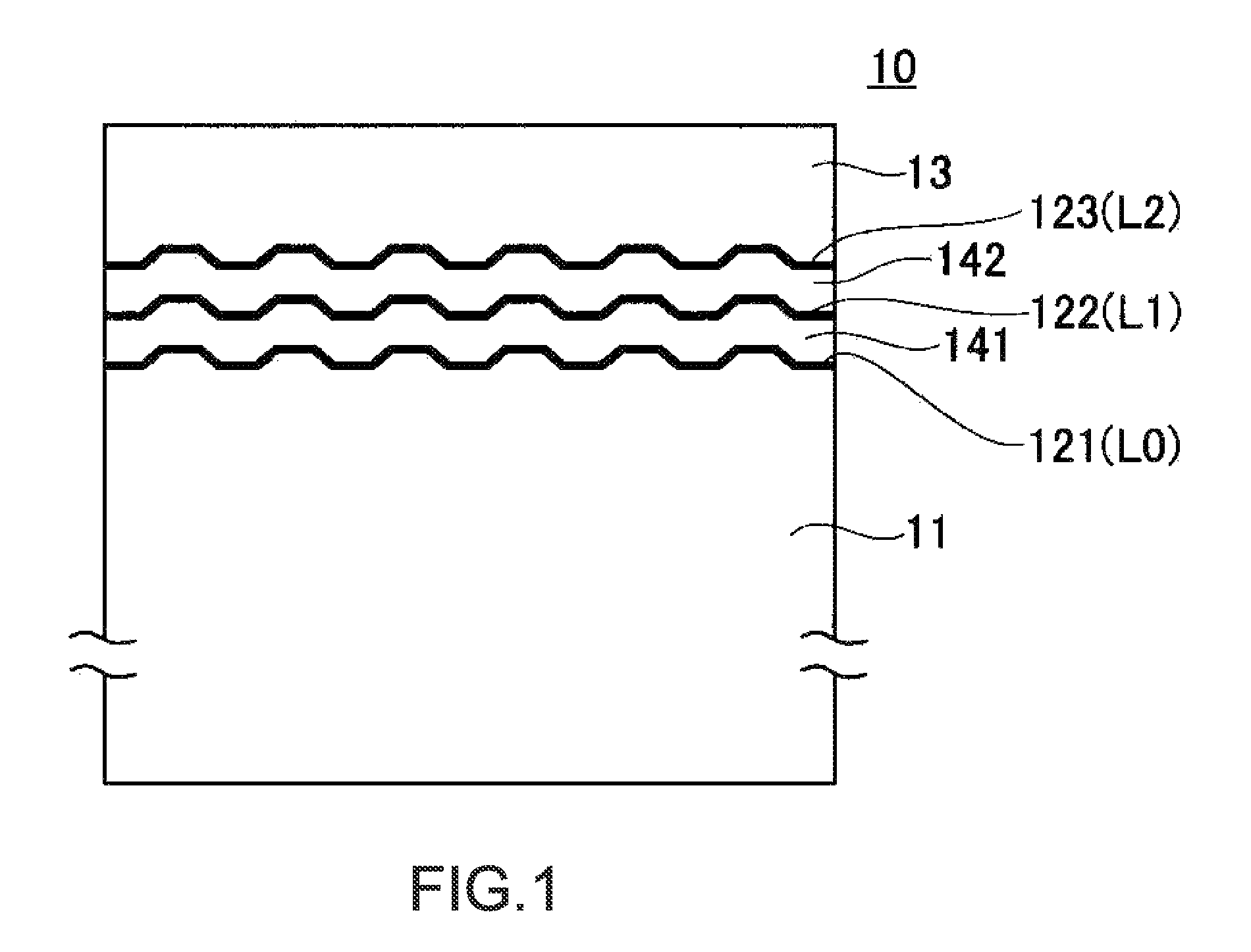
[0030]FIG. 1 shows an schematic configuration diagram (cross-sectional view) of an optical recording medium according to a first embodiment of the present invention.
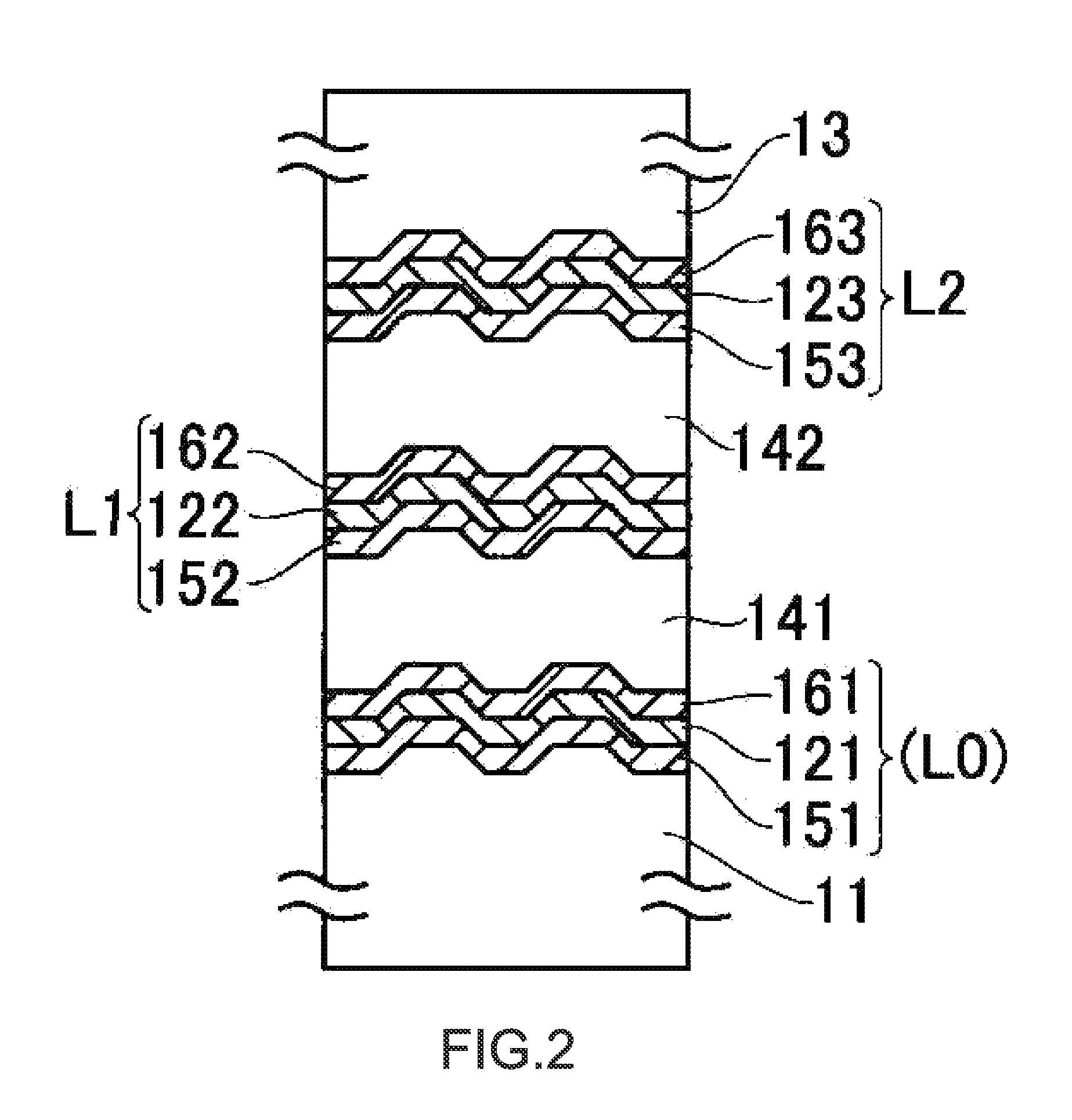
[0031]In this optical recording medium 10, on a substrate 11, three layers of recording layers 121 (L0), 122 (L1), and 123 (L2) are provided. It should be noted that for convenience, L0, L1, and L2 are added to be shown because, in a multi-layered recording medium, a recording layer closest to a substrate is referred to as L0, followed by L1, L2 . . . , normally.
[0032]Moreover, between the recording layers 121, 122, and 123, intermediate layers 141 and 142 that are formed of a light transmissive material are provided.
[0033]Furthermore, on the recording layer 123 being the uppermost layer, a protective layer 13 that is formed of a light transmissive material is provided.
[0034]In the case where the optical recording medium 10 according to this embodiment has the configuration of the high-capacity optical...
second embodiment
2. Second Embodiment
[0074]FIG. 3 shows a schematic configuration diagram (cross-sectional view) of an optical recording medium according to a second embodiment of the present invention.
[0075]In this optical recording medium 20, on a substrate 21, three layers of recording layers 221 (L0), 222 (L1), 223 (L2), and 224 (L3) are provided.
[0076]Moreover, between the recording layers 221, 222, 223, and224, intermediate layers 241, 242, and 243 that are formed of light a transmissive material are provided.
[0077]Furthermore, on the recording layer 224 being the uppermost layer, a protective layer 23 that is formed of light a transmissive material is provided.
[0078]In the case where the optical recording medium 20 according to this embodiment has the configuration of the high-capacity optical disc (BD, registered trademark) described above, the disc-shaped substrate 21 having a thickness of about 1.1 mm and an outer diameter of about 120 mm is used. Then, on a surface side thereof, e.g., on ...
third embodiment
3. Third Embodiment
[0102]FIG. 4 shows a schematic configuration diagram (cross-sectional view) of an optical recording medium according to a third embodiment of the present invention.
[0103]The configuration of the optical recording medium 30 in the case where a recording layer thereof has n (n is an arbitrary natural number of five or more) layers is shown.
[0104]In the optical recording medium 30 according to this embodiment, on a substrate 31, a concavo-convex shape as wobbling grooves is formed, similarly as in the cases of the first embodiment and the second embodiment. Then, on this concavo-convex forming surface, recording layers 321 (L0), 322, (L1), 323 (L2), 324 (L3), . . . , 32n (Ln) are provided via intermediate layers 341, 342, 343, . . . , 34n from the substrate 31 side. On the recording layer 32n (Ln) being the uppermost layer, a protective layer 33 is provided.
[0105]Also in this case, in the case where the optical recording medium 30 has the configuration of the high-ca...
PUM
| Property | Measurement | Unit |
|---|---|---|
| wavelength | aaaaa | aaaaa |
| outer diameter | aaaaa | aaaaa |
| thickness | aaaaa | aaaaa |
Abstract
Description
Claims
Application Information
 - R&D
- Intellectual Property
- Life Sciences
- Materials
- Tech Scout
- Unparalleled Data Quality
- Higher Quality Content
- 60% Fewer Hallucinations
Browse by: Latest US Patents, China's latest patents, Technical Efficacy Thesaurus, Application Domain, Technology Topic, Popular Technical Reports.
© 2025 PatSnap. All rights reserved.Legal|Privacy policy|Modern Slavery Act Transparency Statement|Sitemap|About US| Contact US: help@patsnap.com


