Back structure of thermo-photovoltaic cell

A technology of thermal photovoltaic cells and back, applied in photovoltaic power generation, circuits, electrical components, etc., to achieve the effect of facilitating collection and improving photoelectric conversion efficiency

Pending Publication Date: 2018-09-14
无锡马丁格林光伏科技有限公司
View PDF5 Cites 3 Cited by
  • Summary
  • Abstract
  • Description
  • Claims
  • Application Information

AI Technical Summary

Problems solved by technology

At present, in thermal photovoltaic cells, there are few re...

Method used


Image

  • Back structure of thermo-photovoltaic cell

Examples


Embodiment Construction

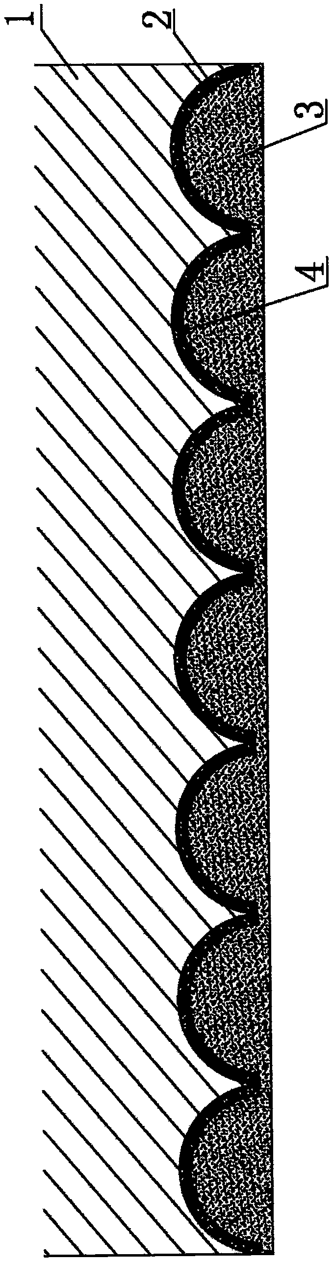
[0008] The present invention will be further explained below in conjunction with the drawings.

[0009] Such as figure 1 As shown, the present invention is a back structure of a thermal photovoltaic cell, including a cadmium telluride layer 1, which is characterized in that a groove 4 is formed on the back of the cadmium telluride layer 1, and 5 to 5 are provided in the groove 4. The silicon dioxide film layer 2 of 10 nanometers has an aluminum layer 3 printed on the surface of the silicon dioxide film layer 2.

[0010] The present invention is obtained through the following steps:

[0011] (1) Use an infrared laser to make a groove 4 on the back of the cadmium telluride layer 1, with a hole diameter of 800-1500 nanometers and a hole depth of 400-750 nanometers;

[0012] (2) Use a certain concentration of hydrofluoric acid to clean the surface of the groove 4;

[0013] (3) Perform thermal oxidation treatment on the surface of the groove 4 to form a 5-10 nanometer silicon dioxide film ...


PUM


Abstract

The invention provides a back structure of a thermo-photovoltaic cell. The back structure comprises a cadmium telluride layer. The back structure is characterized in that a groove is arranged in the back surface of the cadmium telluride layer. A silica dioxide film layer of 5-10nm is arranged in the groove. An aluminum layer is printed on the surface of the silica dioxide film layer. The silica dioxide film layer and the aluminum layer form Mie-scattering to the light reaching the bottom surface and have high backscattering effect so that the photoelectric conversion efficiency of the thermo-photovoltaic cell can be enhanced. The silica dioxide and the aluminum dielectric form the "quantum tunneling effect" so that collection of the carriers can be facilitated and the photoelectric conversion efficiency can be greatly enhanced.

Description

Technical field [0001] The invention belongs to the technical field of solar thermal utilization, and is specifically a back structure of a thermal photovoltaic cell. Background technique [0002] Thermal photovoltaic cells are also called thermoelectric cells, which mainly use infrared light and far-infrared light that account for most of the sunlight to generate electricity. The power generation principle is similar to that of photovoltaics currently on the market. At present, in thermal photovoltaic cells, there are few research reports on the back structure of thermal photovoltaic cells. Summary of the invention [0003] In view of the above problems, the present invention provides a back structure of a thermal photovoltaic cell, which is used on the back of a thermal photovoltaic cell, which can totally reflect infrared light and far-infrared light, so that the light reaching the back is reflected into the battery body to generate electricity again. Greatly improve the conve...

Claims


Application Information

Patent Timeline
IPC IPC(8): H01L31/054
CPCH01L31/0547Y02E10/52
Inventor 熊保鸿
Owner 无锡马丁格林光伏科技有限公司
Why Eureka
Try Eureka