
Device for moving molar to far-middle based on micro-implant anchorage

A technology for micro-implantation and teeth grinding, which is applied in the field of orthodontic treatment and achieves the effects of simple structure, easy manufacture, time saving and economical cost.

Pending Publication Date: 2018-09-18
SICHUAN UNIV
View PDF23 Cites 6 Cited by
  • Summary
  • Abstract
  • Description
  • Claims
  • Application Information

AI Technical Summary

Problems solved by technology

[0004] There are two types of micro-implant anchorage implantation sites, corresponding to two correction methods: one is to implant anchorage nails into the buccal side, use the nickel-titanium push spring on the main arch wire to push the molars to move distally, and use the ligature wire The anchorage nails are ligated to the canines, but in this way, the main archwire needs to be dismantled and the push spring is replaced every time the follow-up visit is made; the other is to implant the anchorage nails in the middle of the palate and bend the modified transverse palate Rod, so that it reaches about 6mm mesial to the anchorage nail, and the two are connected with a chain-shaped rubber ring to increase force. The applied distal movement force passes through the resistance center of the molars, and the molars can be moved distally as a whole, but this method needs to be in the molars Upper placement of the belt loop and additional bending and welding work

Method used


Image

  • Device for moving molar to far-middle based on micro-implant anchorage
  • Device for moving molar to far-middle based on micro-implant anchorage
  • Device for moving molar to far-middle based on micro-implant anchorage

Examples


Embodiment Construction

[0022] In order to make the object, technical solution and advantages of the present invention clearer, the present invention will be further described in detail below in conjunction with the accompanying drawings.

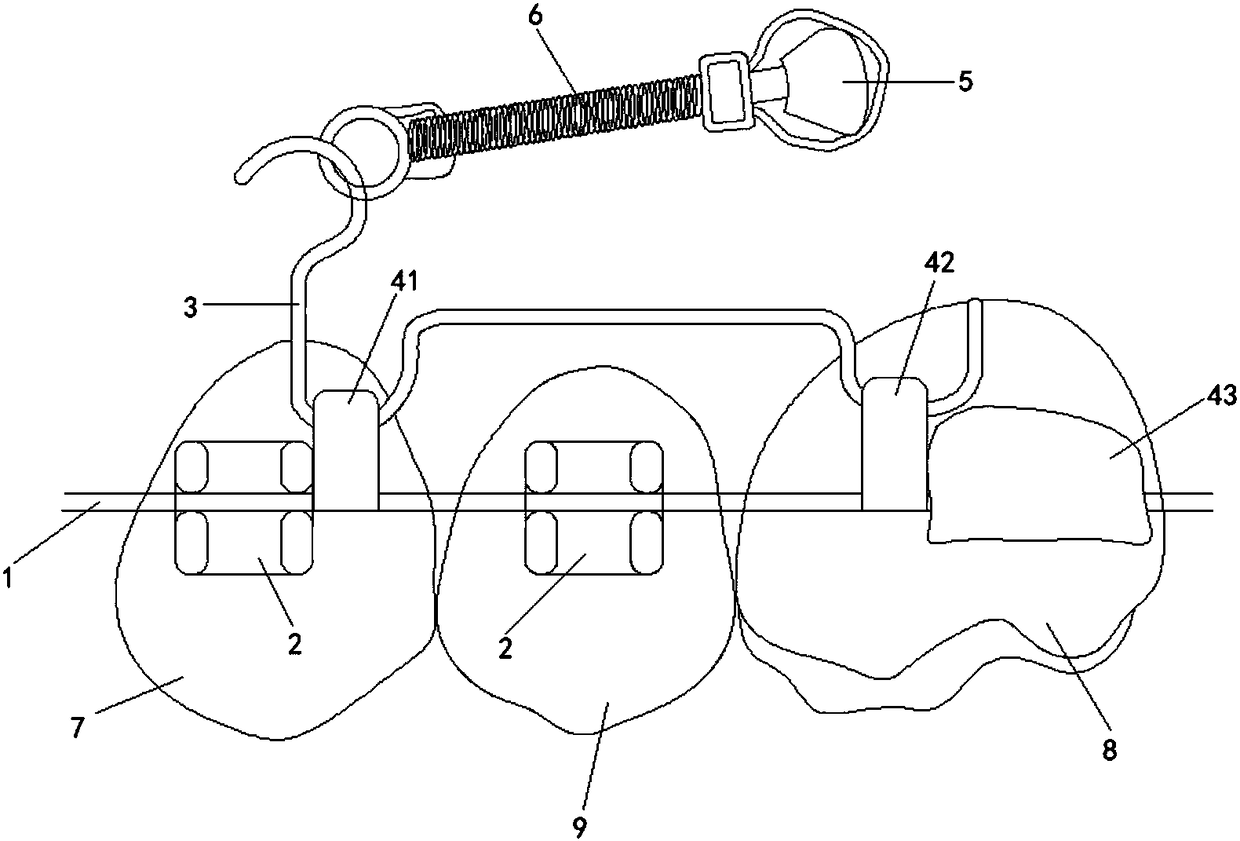
[0023] figure 1 It is a diagram of the use state of the embodiment of the present invention, including: a main arch wire 1, a metal wire used to guide the movement of teeth; a bracket 2, attached to an orthodontic object; the main arch wire 1 passes through the bracket 2 in turn and fixed in the groove of the bracket 2; it also includes: auxiliary arch wire 3, buccal tube, anchorage element 5, and force applying element 6.

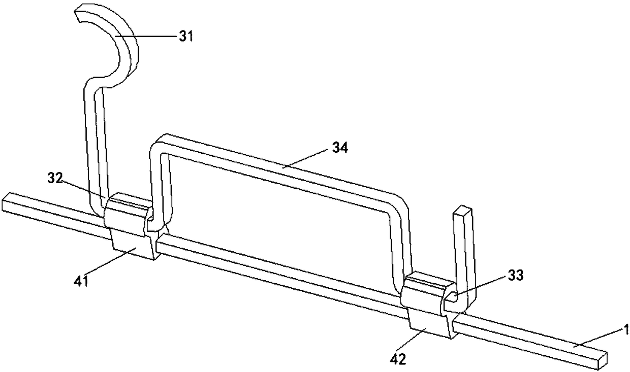
[0024] There are three buccal tubes, the first buccal tube 41 is attached to the first premolar 7, the second buccal tube 42 is attached to the first molar 8; the auxiliary arch wire 3 is used to connect the first buccal tube 41 and the second buccal tube 42, and the auxiliary arch wire 3 is located above the bracket of the second premolar 9;...


PUM

PropertyMeasurementUnit
The inside diameter ofaaaaaaaaaa
Radianaaaaaaaaaa

Abstract

The invention discloses a device for moving a molar to far-middle based on a micro-implant anchorage. The device comprises a main arch wire, a bracket, an auxiliary arch wire, buccal tubes, an anchorage element, and a force applying element. The number of buccal tubes is three, the first buccal tube is attached to a first premolar, and the second buccal tube is attached to a first molar. The auxiliary arch wire is used for connecting the first buccal tube and the second buccal tube, and the auxiliary arch wire is positioned above the bracket of a second premolar. The first molar is further attached to the third buccal tube. The first buccal tube is tightly adjacent to the far-middle end of the bracket of the first premolar, and the second buccal tube is tightly adjacent to the near-middleend of the third buccal tube. The main arch wire passes through the first buccal tube, the second buccal tube and the third buccal tube, and is fixed in the above buccal tubes. The force applying element is connected with the anchorage element, and applies a traction force parallel to the main arch wire to the auxiliary arch wire. The traction force points to a far-middle direction. The provided technical scheme is capable of simply and effectively moving the molar to the far-middle, and saving time and reducing economic cost for a clinic operation.

Description

technical field [0001] The invention relates to the technical field of orthodontics, in particular to a device for moving molars distally based on micro-implant anchorages. Background technique [0002] With the development of the economy and the progress of society, more and more people choose to receive orthodontic treatment for aesthetic or functional reasons. In clinical work, orthodontists apply force to teeth, jaws or temporomandibular joints through various appliances, so that the teeth can be tilted, integrated, root-controlled, vertical (elongated or depressed) or rotated to make the jaws The shape and position are rebuilt, so as to achieve the established correction effect and the goal of balance, beauty and stability. [0003] In the face of complex dentofacial deformities, orthodontists often need to move the molars distally to provide a basis for aligning interdental spaces, leveling the dentition, and adjusting the occlusal relationship. However, in tradition...

Claims


Application Information

Patent Timeline
IPC IPC(8): A61C7/28
CPCA61C7/28A61C7/282Y02A50/30
Inventor 刘钧夏恺邹玲孙闻天余丽媛
Owner SICHUAN UNIV
Learn More