
Energy-saving and environmental-friendly biomass fuel manufacturing device

A technology of biomass fuel and manufacturing equipment, applied in the direction of biofuel, waste fuel, fuel, etc.

Active Publication Date: 2018-09-18
浙江蓝天知识产权运营管理有限公司
View PDF6 Cites 3 Cited by
  • Summary
  • Abstract
  • Description
  • Claims
  • Application Information

AI Technical Summary

Problems solved by technology

[0002] For example, the patent number CN201710689934.4 is a kind of biomass fuel manufacturing equipment, including a device body, the upper end of the device body is provided with a feed port, and the feed port is embedded in the device body, and the front end of the device body An observation port is installed above, and a reducer is installed at the lower end of the observation port, and the reducer is embedded in the device body, and a feeding port and a discharge port are installed on the right side of the device body. The original button opens the hole and observes the condition of the heat from a long distance with the naked eye, avoiding the shortcomings of burnt raw materials that are overheated and immature raw materials that are underfired, and the conditioner is connected to the feed port. It can conveniently adjust and temper different raw materials between equipments, which effectively improves the usability of the equipment. At the same time, the granulation room is used to transfer the raw materials to the room to make granules, which effectively improves the reliability of the granulation room. The disadvantage of this invention is that the machine cannot automatically pack the biomass fuel by weight

Method used


Image

  • Energy-saving and environmental-friendly biomass fuel manufacturing device
  • Energy-saving and environmental-friendly biomass fuel manufacturing device
  • Energy-saving and environmental-friendly biomass fuel manufacturing device

Examples


specific Embodiment approach 1

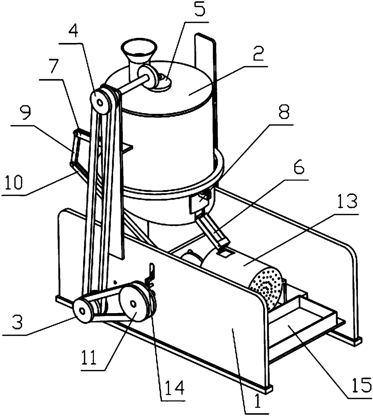
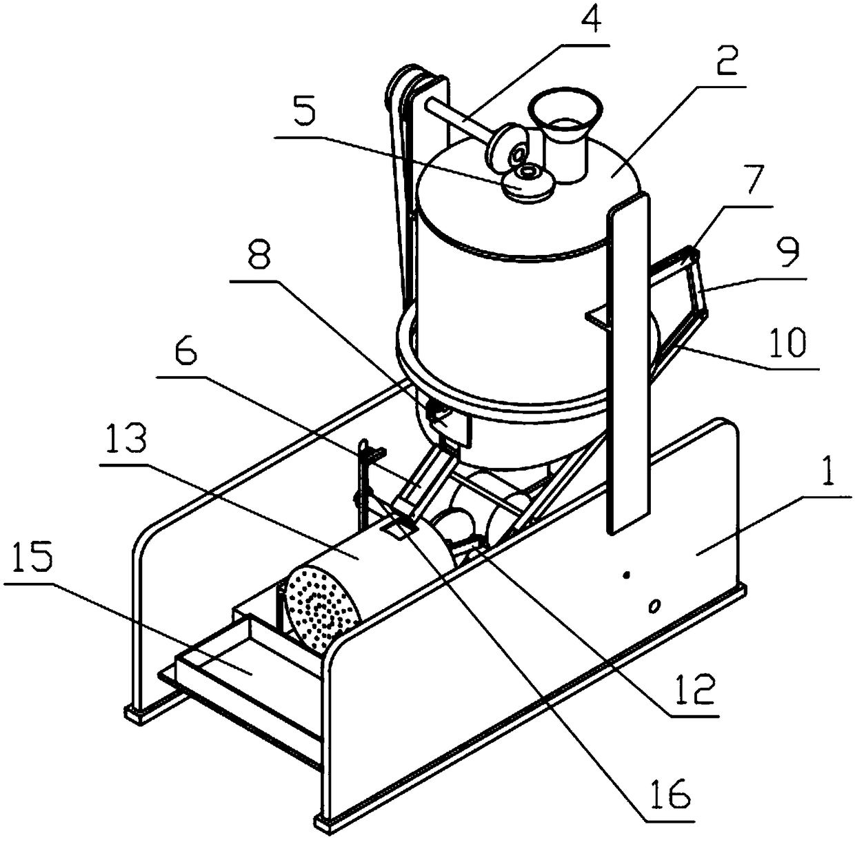
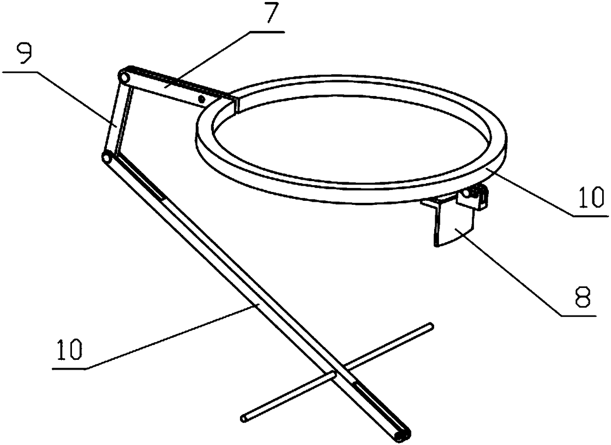
[0040] Combine below Figure 1-18 Describe this embodiment, an energy-saving and environment-friendly biomass fuel manufacturing equipment, complete machine bracket 1, feeding plate 2, power mechanism 3, transmission mechanism 4, crushing mechanism 5, connecting bracket 6, circular connecting rod 7, sliding block Plate 8, short connecting rod 9, long connecting rod 10, extruding mechanism 11, extruding connecting rod 12, extruding bracket 13, shift fork 14, storage box 15 and vortex spring 16, described feeding plate 2 is fixedly connected On the complete machine support 1, the feeding plate 2 communicates with the inside of the complete machine support 1, the power mechanism 3 is fixedly connected on the complete machine support 1, and the transmission mechanism 4 is rotatably connected on the complete machine support 1. The power mechanism 3 and the transmission mechanism 4 Connected by belt transmission, the crushing mechanism 5 is rotatably connected to the whole machine s...

specific Embodiment approach 2

[0041] Combine below Figure 1-18 This embodiment will be described. This embodiment will further describe the first embodiment. The complete machine bracket 1 includes a side plate 1-1, an extruded support plate 1-2, a crushing shell 1-3 and a circular through hole II 1-4. The crushing shell 1-3 includes the crushing shell 1-3-1, the sliding groove I 1-3-2, the discharge port 1-3-3 and the connecting rod support 1-3-4, and the crushing shell 1-3-1 The lower end is inclined, and there are two sliding grooves I1-3-2, and the two sliding grooves I1-3-2 are respectively arranged at the lower end of the right side of the crushing shell 1-3, and the connecting rod support 1-3-4 is welded to the crushing shell The left end of 1-3, the discharge port 1-3-3 is set at the lower end of the right side of the crushing shell 1-3, two circular through holes I are set on the extrusion support plate 1-2, and the side plate 1-1 is set There are two, the two ends of the extrusion support plate...

specific Embodiment approach 3

[0042] Combine below Figure 1-18 Describe this embodiment, this embodiment will further explain Embodiment 2, the feed plate 2 includes a feed base 2-1 and a feed inlet bracket 2-2, and the feed inlet bracket 2-2 is welded on the feed base 2-1, the feeding bottom plate 2-1 is fixedly connected to the upper end of the crushing shell 1-3-1, and the feed inlet bracket 2-2 communicates with the interior of the crushing shell 1-3-1.


PUM


Abstract

The invention relates to a manufacturing device, and more specifically, relates to an energy-saving and environmental-friendly biomass fuel manufacturing device comprising a whole machine bracket, a feeding plate, a power mechanism, a transmission mechanism, a crushing mechanism, a connecting bracket, a circular connecting rod, a sliding baffle, a short connecting rod, a long connecting rod, an extrusion mechanism, an extrusion connecting rod, an extrusion bracket, a shifting fork and containing boxes; biomass can be subjected to crushing treatment, and the biomass having crushing treatment completed can enter the extrusion bracket through the connecting bracket; when the biomass in the extrusion bracket reaches a certain weight, the extrusion bracket extrudes a compression spring to movedownward to drive the sliding baffle to block a discharge outlet, and the biomass cannot enter the extrusion bracket; when the extrusion bracket moves downward, side teeth are pushed to be meshed withan extrusion pulley, an extrusion shaft transmits power to drive an extrusion crank to rotate to push an extrusion plate wheel to extrude the biomass to mold; when the containing boxes are taken down, a vortex spring extrudes the extrusion crank to reset, and the masses of the molded biomass in all the containing boxes are the same.

Description

technical field [0001] The invention relates to a manufacturing equipment, more specifically to an energy-saving and environment-friendly biomass fuel manufacturing equipment. Background technique [0002] For example, the patent number CN201710689934.4 is a kind of biomass fuel manufacturing equipment, including a device body, the upper end of the device body is provided with a feed port, and the feed port is embedded in the device body, and the front end of the device body An observation port is installed above, and a reducer is installed at the lower end of the observation port, and the reducer is embedded in the device body, and a feeding port and a discharge port are installed on the right side of the device body. The original button opens the hole and observes the condition of the heat from a long distance with the naked eye, avoiding the shortcomings of burnt raw materials that are overheated and immature raw materials that are underfired, and the conditioner is conne...

Claims


Application Information

Patent Timeline
Patent Type & Authority Applications(China)
IPC IPC(8): C10L5/44B01J2/20B02C19/22B65B1/30
CPCB01J2/20B02C19/22B65B1/30C10L5/44Y02E50/10Y02E50/30
Inventor 刘贵学
Owner 浙江蓝天知识产权运营管理有限公司
Learn More