
Method and apparatus for producing group iii nitride

a technology of nitride and group iii, which is applied in the direction of polycrystalline material growth, crystal growth process, chemically reactive gas growth, etc., can solve the problems of substantially impossible to grow a group iii nitride on the substrate, low yield, etc., and achieve high yield, high productivity, and the effect of the same quality

Inactive Publication Date: 2010-02-04
TOKUYAMA CORP
View PDF4 Cites 18 Cited by
  • Summary
  • Abstract
  • Description
  • Claims
  • Application Information

AI Technical Summary

Benefits of technology

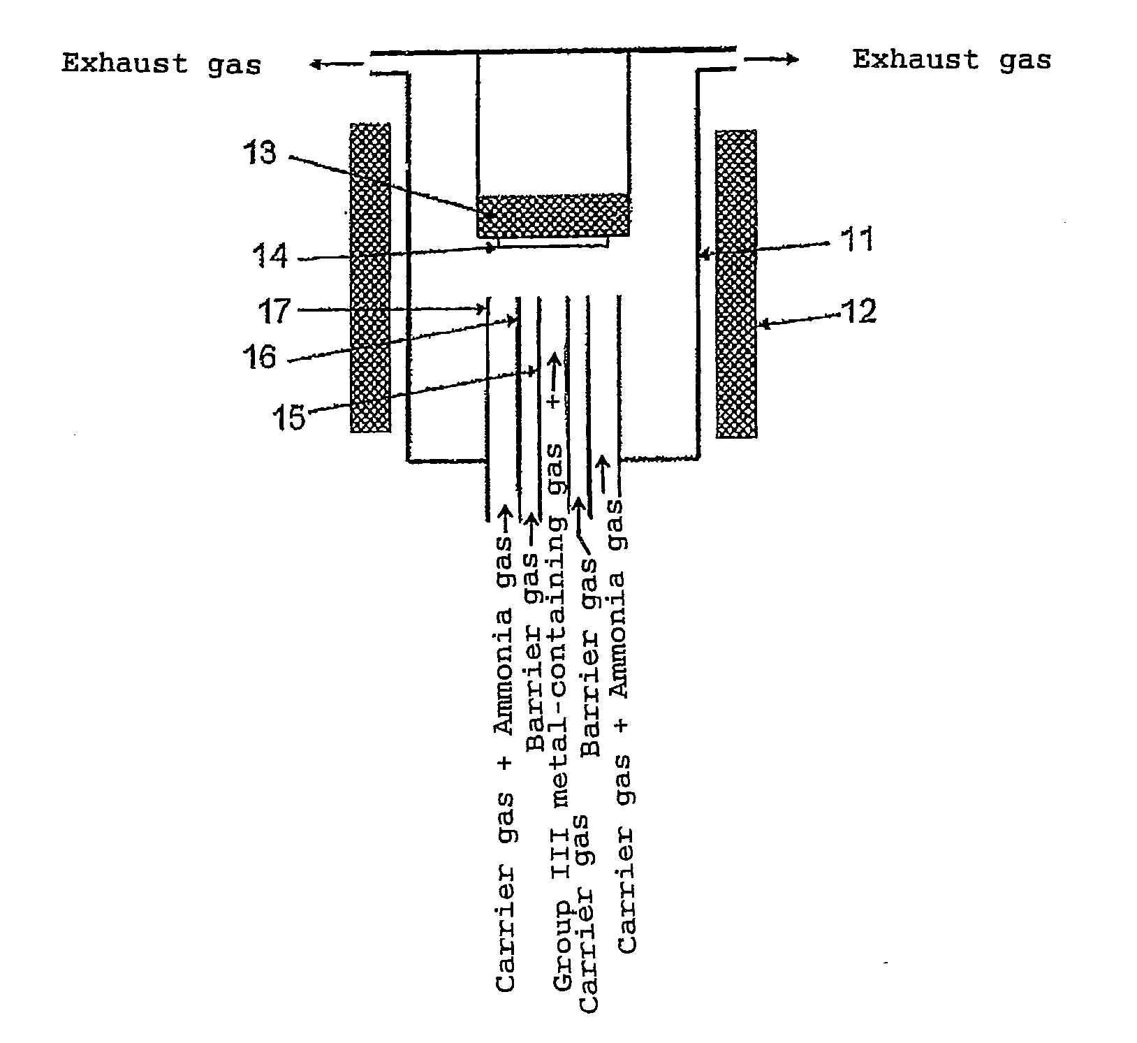
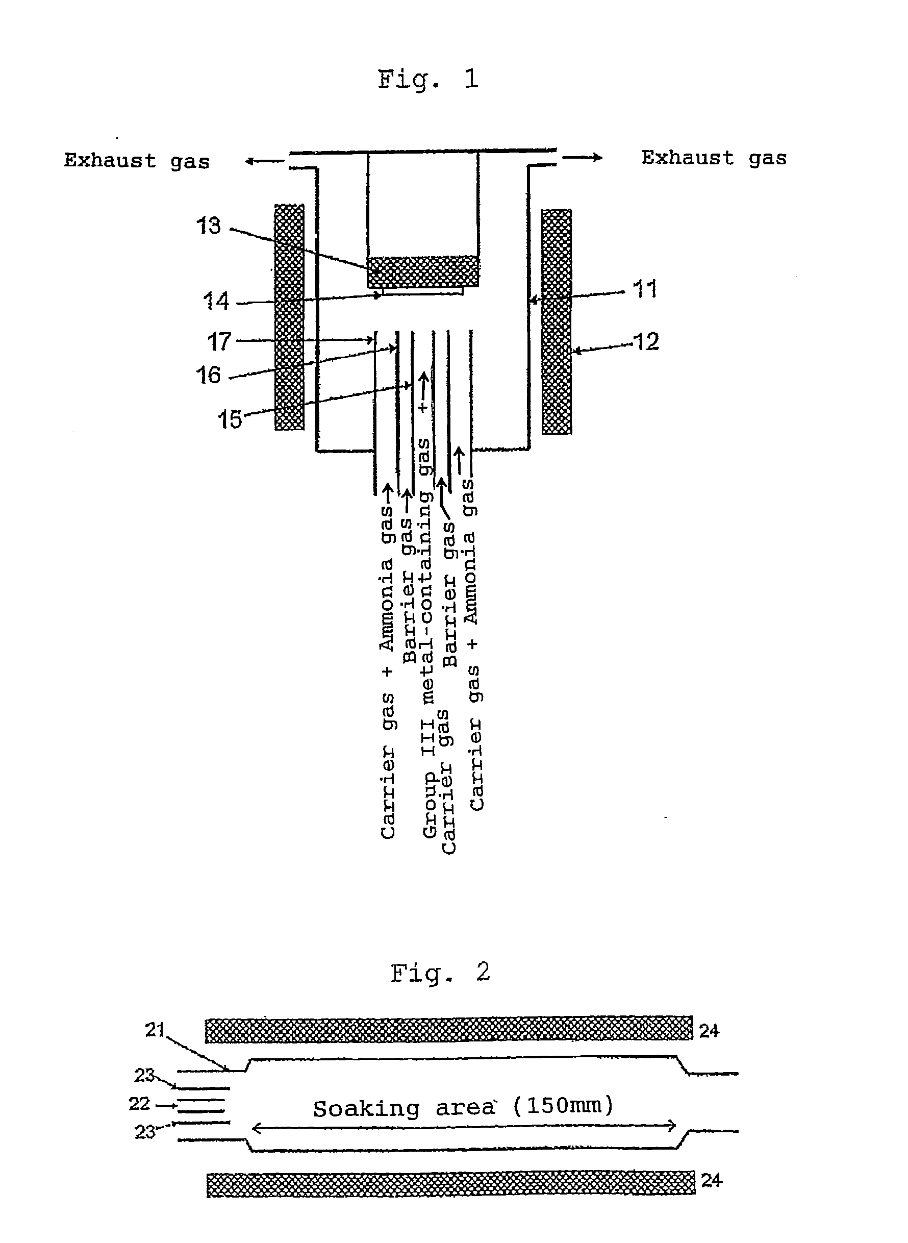
[0016]It is an object of the present invention to provide a method and apparatus for producing a group III nitride having the same quality as that obtained by the conventional method at a high yield, that is, a high productivity when a group III nitride such as an aluminum-based group III nitride is grown by HVPE.
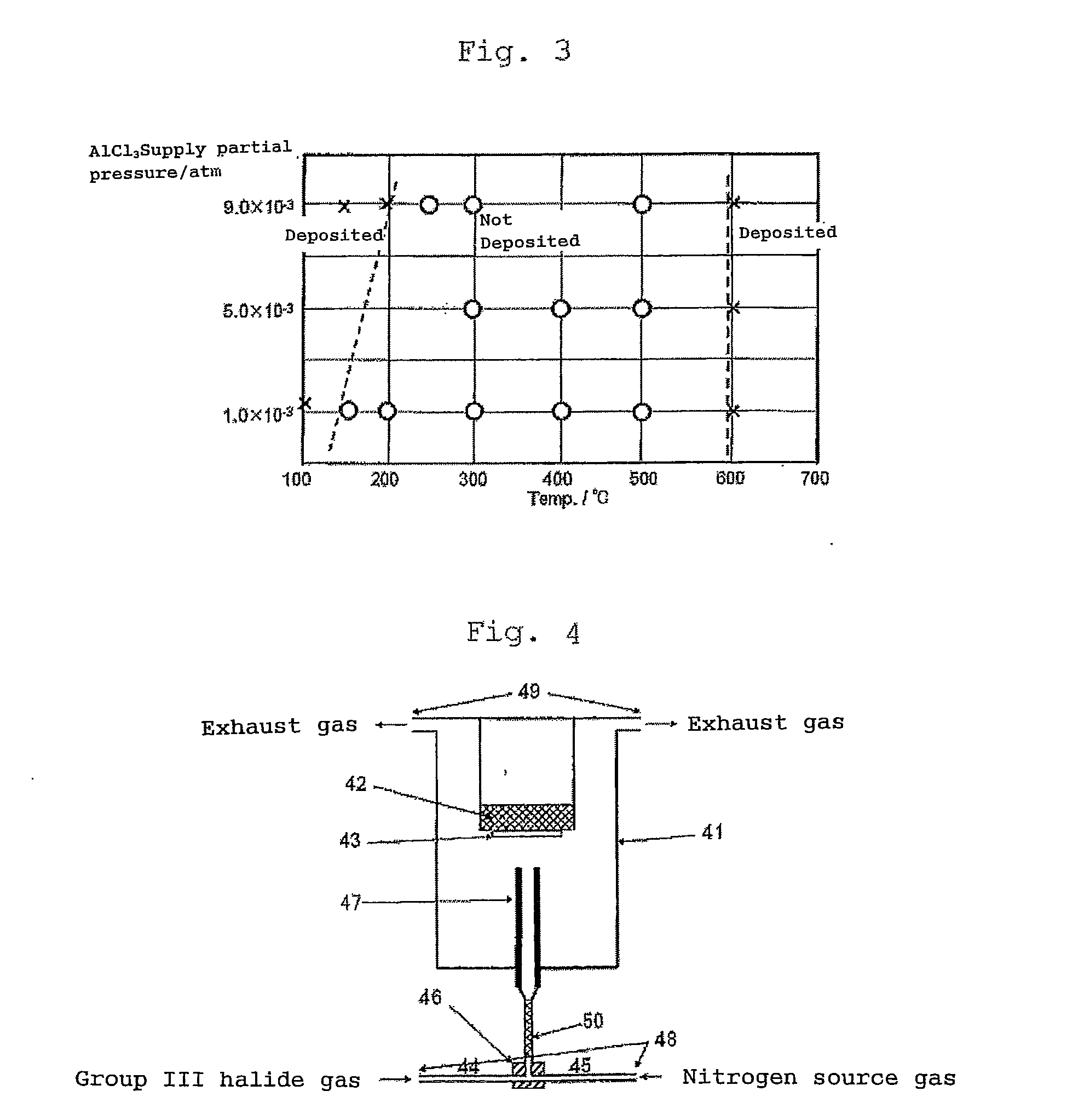
[0021]In the above method, mixing of the group III halide gas and the nitrogen source gas in the above premixing step is carried out at a temperature T (° C.) ranging from the lower limit temperature specified by the following mathematical expression (1) to lower than 600° C. when the supply partial pressure of the group III halide gas to be supplied is represented by P (atm), and the mixed gas is introduced into the growth chamber by keeping the temperature of the obtained mixed gas at a range from the above lower limit temperature to lower than 600° C., thereby making it possible to introduce the mixed gas into the growth chamber without forming a deposit substantially and therefore to blow it against the substrate directly. Therefore, the yield can be greatly improved.T=-2.40×1000logP-3.03-273.15(1)

Problems solved by technology

As a result, they found that the yield was low because a group III raw material gas and a nitrogen source gas were not uniformly mixed together before they reached the substrate and a mixed gas of these gases did not contact the substrate efficiently in HVPE of the prior art in which these gases are separately introduced into a growth chamber and mixed together in the growth chamber.
When they tried this method, they found that a solid component deposited in the pipe or the ejection port of the nozzle, thereby making it substantially impossible to grow a group III nitride on the substrate.

Method used


Image

  • Method and apparatus for producing group iii nitride
  • Method and apparatus for producing group iii nitride
  • Method and apparatus for producing group iii nitride

Examples


example 1

[0079]A reaction for growing a single crystal of aluminum nitride which is one of group III nitrides was carried out by using the apparatus shown in FIG. 4. Aluminum trichloride was used as the group III halide gas. The aluminum trichloride was formed by reacting hydrogen chloride with metal aluminum maintained at 500° C. on the upstream (not shown) side of the pipe 44 and supplied. An ammonia gas was used as the nitrogen source gas. A ribbon heater was wound round the pipe 44, the pipe 45, the line mixer 50 and the gas mixer 46 to heat them at 300° C. to be maintained. The nozzle 47 was made of stainless steel (SUS316L) and had a structure that heating oil could be circulated in the nozzle (temperature control nozzle) to circulate the oil heated at 300° C. so as to maintain the nozzle at that temperature. At this point, the distance between the end of the nozzle 47 and the surface of the substrate 43 was 25 mm. A sapphire c-plane substrate having a diameter of 2 inches was used as ...

example 2

[0082]The operation of Example 1 was repeated except that the temperature for heating the substrate was changed to 1,600° C.

[0083]The raw material mixed gas was supplied onto the substrate for 60 minutes to grow an aluminum nitride single crystal on the substrate. After 60 minutes, the supply of only the aluminum trichloride gas was stopped to terminate the growth of aluminum nitride. After the substrate was cooled to 500° C., the supply of the ammonia gas was stopped and the substrate was further cooled to room temperature and then taken out to be evaluated. As a result, a weight change by aluminum nitride grown on the substrate was an increase of 0.0925 g from that before growth, the average film thickness of aluminum nitride was 14 μm, and the crystal growth speed was 14 μm / hr in terms of film forming speed. The mass of the group III metal immobilized on the substrate (the mass of the immobilized group III metal) was 0.0023 mol. Since the mass of the group III halide gas supplied...

example 3

[0084]The operation of Example 1 was repeated using the apparatus shown in FIG. 4 except that the distance between the nozzle 47 and the surface of the substrate 43 in FIG. 4 was changed to 10 mm and the temperature of the temperature control nozzle was changed to 200° C.

[0085]The raw material mixed gas was supplied onto the substrate for 180 minutes to grow an aluminum nitride crystal on the substrate. After 180 minutes, the supply of only the aluminum trichloride gas was stopped to terminate the growth of aluminum nitride. After the substrate was cooled to 500° C., the supply of the ammonia gas was stopped and the substrate was further cooled to room temperature and then taken out to be evaluated. As a result, a weight change by aluminum nitride grown on the substrate was an increase of 0.6870 g from that before growth, the average film thickness of aluminum nitride was 104 μm, and the crystal growth speed was 35 μm / hr in terms of film forming speed. The mass of the group III meta...


PUM

PropertyMeasurementUnit
temperatureaaaaaaaaaa
distanceaaaaaaaaaa

Abstract

A method of producing a group III nitride such as aluminum nitride, comprising the step of reacting a group III halide gas such as aluminum trichloride gas with a nitrogen source gas such as ammonia gas in a growth chamber to grow a group III nitride on a substrate held in the growth chamber, wherein the method further comprises premixing together the group III halide gas and the nitrogen source gas to obtain a mixed gas and then introducing the mixed gas into the growth chamber without forming a deposit in the mixed gas substantially to be reacted each other.For the growth of a group III nitride such as an aluminum-based group III nitride by HVPE, there are provided a method of producing the group III nitride having as high quality as that obtained by the method of the prior art at a high yield and an apparatus used in the method.

Description

TECHNICAL FIELD[0001]The present invention relates to a method and apparatus for producing a group III nitride from a group III halide gas by a chemical vapor deposition technique.BACKGROUND ART[0002]Group III nitride semiconductor crystals such as aluminum nitride, gallium nitride and indium nitride have a wide range of band gap energy and the band gap energy values of these substances are about 6.2 eV, about 3.4 eV and about 0.7 eV, respectively. A mixed crystal semiconductor having any composition can be formed from these group III nitride semiconductors, thereby making it possible to obtain a band gap energy value between the above band gap energy values according to the composition of the mixed crystal.[0003]Therefore, it is theoretically possible to manufacture a light emitting device which emits a wide range of light from infrared light to ultraviolet light by using the group III nitride semiconductor crystals. Particularly, the development of a light emitting device using an...

Claims


Application Information

Patent Timeline
Patent Type & Authority Applications(United States)
IPC IPC(8): H01L21/20C23C16/54
CPCC23C16/303C23C16/45512C23C16/45514C23C16/45519C23C16/4557H01L21/0262C30B25/14C30B25/16C30B29/403H01L21/0254C30B25/02
Inventor NAGASHIMA, TORUTAKADA, KAZUYAYANAGI, HIROYUKIHARADA, MANABUHIRATA, YASUNORIKONDO, KEISUKE
Owner TOKUYAMA CORP
Learn More