Independent unmanned aerial vehicle landing method and system based on two-dimensional code and inertial navigation assistance
A technology of two-dimensional codes and drones, applied in control/regulation systems, instruments, vehicle position/route/height control, etc., can solve the problem that two-dimensional codes do not contain any other information, are not robust, Code loss and other problems, to achieve the effects of not being easily disturbed by the environment, improving system robustness, and being easy to operate
- Summary
- Abstract
- Description
- Claims
- Application Information
AI Technical Summary
Problems solved by technology
Method used
Image


Examples
Embodiment Construction
[0042] In order to more clearly illustrate the technical solutions in the prior art, the specific implementation manners of the present invention will be described below with reference to the accompanying drawings. Obviously, the following descriptions are only some embodiments of the present invention, and those skilled in the art can also obtain other drawings and obtain other implementations based on these drawings without creative work. Way.
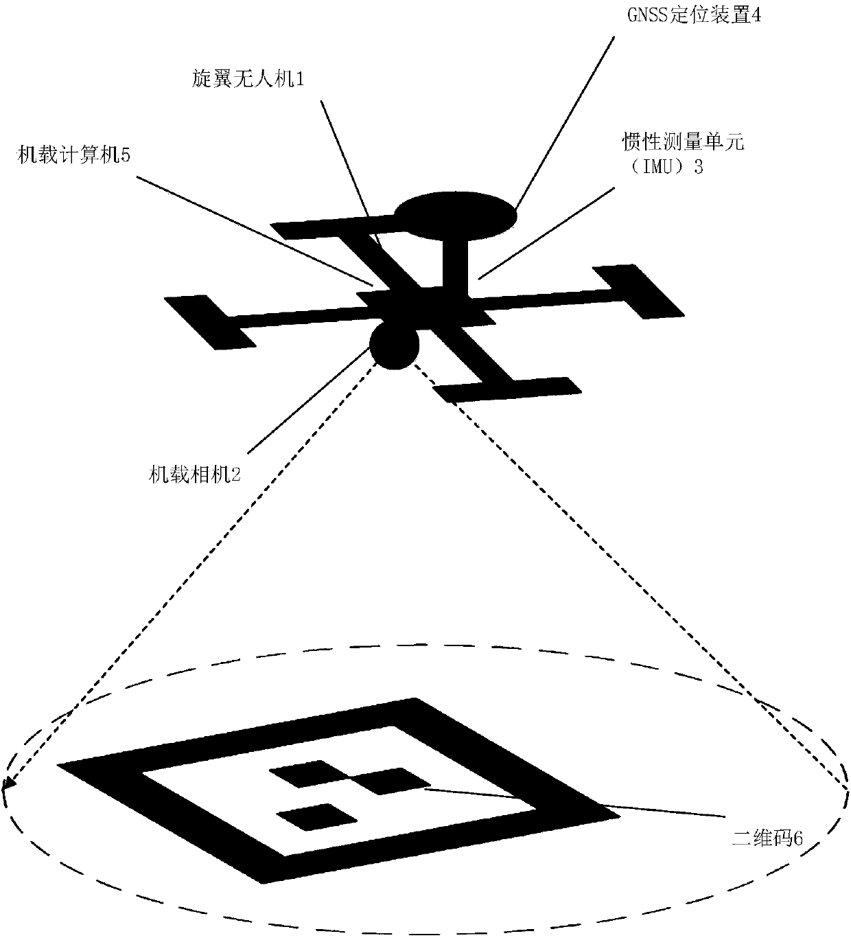
[0043] The present invention proposes to provide a high-precision, low-cost, safe and reliable UAV autonomous landing system based on the two-dimensional code containing authorization information, using the camera carried by the UAV, the inertial sensor and the GNSS receiver. The system consists of figure 1 As shown, it includes a drone 1 , an onboard camera 2 , an inertial measurement unit (IMU) 3 , a GNSS positioning device 4 , an onboard computer 5 , and a two-dimensional code 6 .
[0044] The unmanned aerial vehicle 1 can adopt...
PUM
 Abstract
Description
Claims
Application Information