
Piezoelectric thermoelectric dynamic isotope cell

An isotope battery, electrothermoelectric technology, which is applied in the fields of obtaining electrical energy from radioactive sources, nuclear engineering, and the application of radiation from radioactive sources, etc. question

Active Publication Date: 2018-09-18
深圳热电新能源科技有限公司
View PDF6 Cites 7 Cited by
  • Summary
  • Abstract
  • Description
  • Claims
  • Application Information

AI Technical Summary

Problems solved by technology

[0004] The research results of the above four types of isotope batteries show that the low energy conversion efficiency is still the common feature of current isotope batteries
The development of static thermoelectric isotope batteries mainly benefits from the research and development at the national level, especially the design and manufacture of radioisotope thermoelectric generators (RTG) in the United States. The energy conversion efficiency is low, even the latest NASA report enhanced multi-mission radioisotope thermoelectric generators (eMMRTG) has a conversion efficiency of less than 8%, so its application range is limited and the process of civilian use is relatively difficult
However, traditional dynamic isotope batteries are based on turbines or heat engines to generate electricity, and there are technical bottlenecks such as the difficulty in lubrication of high-speed running parts, and the inertia vector generated by high-speed rotation affects the stability of the system, so it has not been practically applied.
In summary, the research on dynamic isotope batteries still needs to be in-depth

Method used


Image

  • Piezoelectric thermoelectric dynamic isotope cell
  • Piezoelectric thermoelectric dynamic isotope cell
  • Piezoelectric thermoelectric dynamic isotope cell

Examples


Embodiment Construction

[0036] Embodiments of the present application are described in detail below. The embodiments described below are exemplary and are only used for explaining the present application, and should not be construed as limiting the present application. If no specific technique or condition is indicated in the examples, it shall be carried out according to the technique or condition described in the literature in this field or according to the product specification. The reagents or instruments used were not indicated by the manufacturer, and they were all commercially available conventional products.

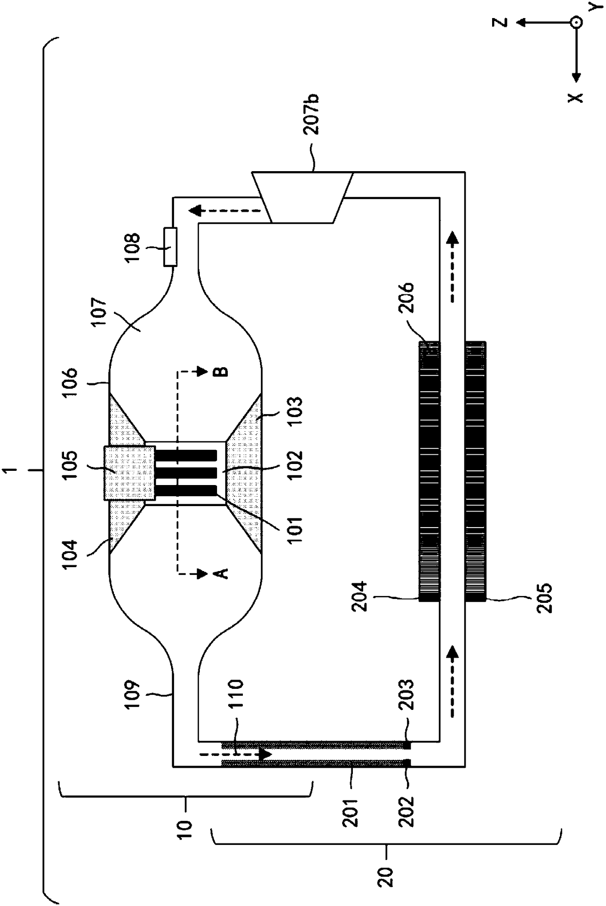
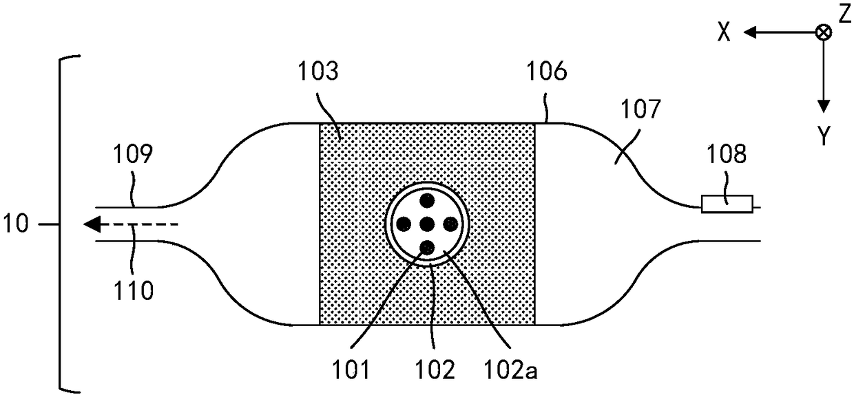
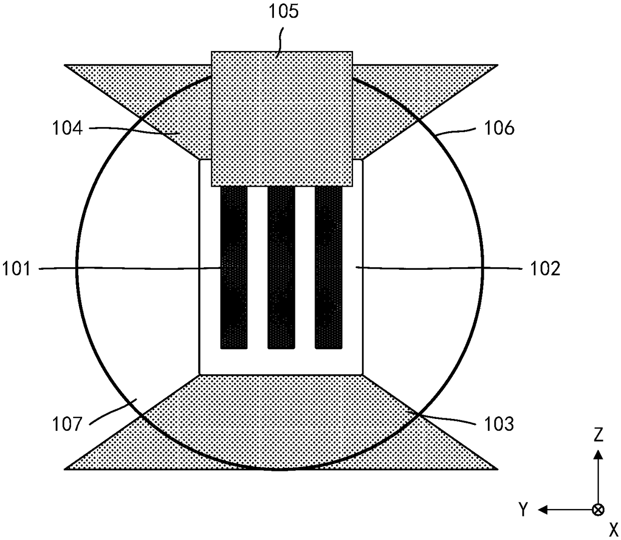
[0037] In one aspect of the present application, the present application proposes a dynamic isotope battery. According to the embodiment of the application, refer to figure 1 , the dynamic isotope battery 1 includes: a gas pipeline 109; a heat source cavity casing 106, the heat source cavity casing 106 defines a heat source cavity 107, and the opposite ends of the heat source cavity c...


PUM


Abstract

The invention provides a piezoelectric thermoelectric dynamic isotope cell. The cell comprises a gas pipeline, a heat source cavity covering case, a fuel box, a radioactive source, a gas state workingmedium, a thermoelectric energy conversion assembly and a single-cavity compressor. The opposite two ends of the heat source cavity cover communicate with the two ends of the gas pipeline so that a closed circulation pipeline is formed. A unidirectional gas charging valve is arranged on the heat source cavity covering case. The fuel box is fixedly arranged in the heat source cavity covering case.The radioactive source is arranged in the fuel box. The gas state working medium fills the circulation pipeline. The piezoelectric energy conversion assembly is arranged on the inner surface of the gas pipeline. The piezoelectric energy conversion assembly is arranged on the outer surface of the gas pipeline and separated from the piezoelectric energy conversion assembly. The single-cavity compressor is arranged on the gas pipeline and used for driving the gas state working medium to flow in a circulation manner. Thus, the cell is highly stable, high in energy conversion efficiency, high in working stability, and quite long in service lifetime and the output power is adjustable.

Description

technical field [0001] The application belongs to the fields of piezoelectric devices, thermoelectric devices and isotope batteries, and specifically relates to piezoelectric thermoelectric dynamic isotope batteries based on gaseous working fluid. Background technique [0002] The isotopes whose nuclear composition (or energy state) changes spontaneously and emit radiation are called radioactive isotopes. The radioactive dynamic isotope battery, referred to as the dynamic isotope battery, uses a transducing component to convert the energy of the radiation released by the radioactive isotope decay into electrical energy output, so as to achieve the purpose of power supply. Due to the advantages of long service life, strong environmental adaptability, good working stability, no maintenance, and miniaturization, isotope batteries have been widely used in important fields such as military defense, deep space and deep sea, polar exploration, biomedicine, and electronics industry....

Claims


Application Information

Patent Timeline
IPC IPC(8): G21H1/00
CPCG21H1/00
Inventor 何佳清周毅孙鑫娄晴于灏
Owner 深圳热电新能源科技有限公司
Learn More