Vacuum drying box for quickly drying extract
A rapid drying and drying oven technology, applied in evaporator accessories, evaporation, chemical instruments and methods, etc., can solve the problems of high manufacturing cost and operating cost, slow drying of extract, avoid pollution, peel off without residue, save money The effect of production costs
- Summary
- Abstract
- Description
- Claims
- Application Information
AI Technical Summary
Problems solved by technology
Method used
Image
Examples
Embodiment 1
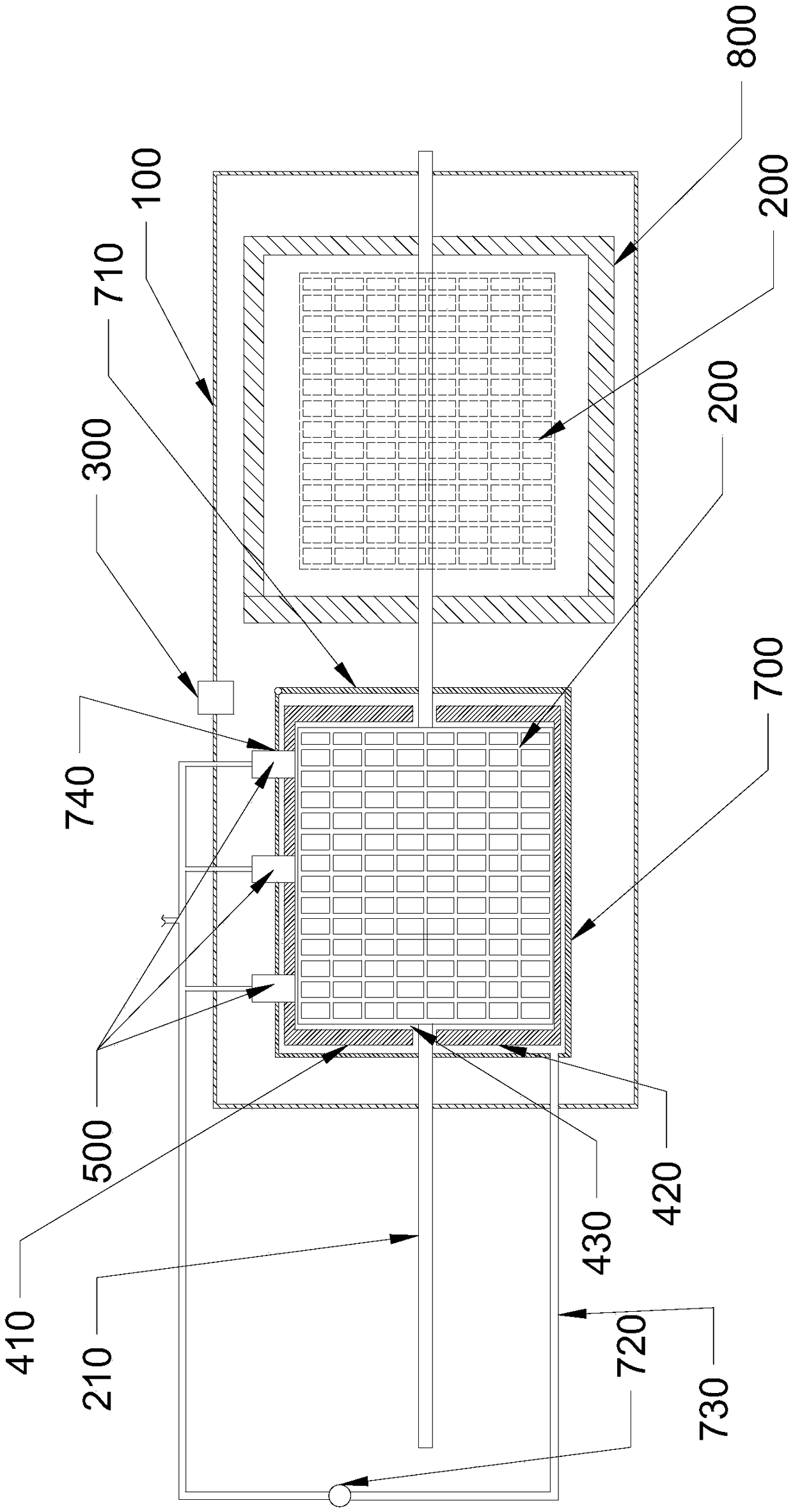
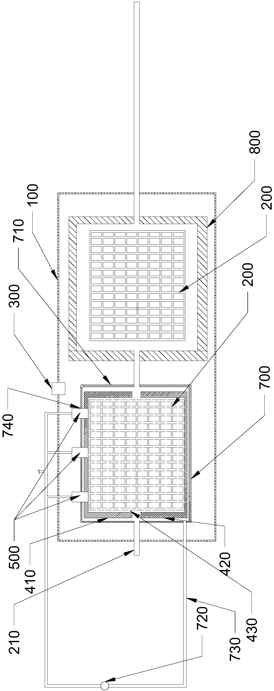
[0047] A kind of decompression drying box of quick-drying extract, see Figure 1-Figure 3 , including a box body 100, a vacuum device 300, a heating device, a spray device 500, an attachment member 200, a peeling drive device and a collection device, wherein:
[0048] The vacuum device 300 is installed on the box body 100, and is used to extract the air in the box body 100 to the outside of the box body 100;
[0049] The heating device is located in the box 100 and is used to heat the air in the box 100;
[0050] The spraying device 500 is arranged in the box 100, and is used for spraying the liquid extract;
[0051] The attachment member 200 is arranged in the box body 100 for receiving the extract sprayed by the spraying device 500;
[0052]The peeling driving device is arranged in the box body 100, and is used to peel off the medicinal paste attached to the attachment member 200 after drying;
[0053] The collection device is arranged in the box 100 for collecting the so...
Embodiment 2
[0058] On the basis of Implementation 1, this embodiment also includes a controller installed on the box 100, the control terminal of the vacuum device 300, the control terminal of the heating device, and the control terminal of the spray device 500 terminal, the control terminal of the peeling driving device, and the control terminal of the feeding power device are all connected to the controller with signals. The controller is set, the operating status of the vacuum device 300, the operating status of the heating device, the operating status of the spraying device 500, the operating status of the stripping driving device and the operating status of the returning power device are all under the instructions stored in the controller Execute in the above order to meet the needs of automation operations.
[0059] It should be noted that when stripping, such as figure 2 As shown, the rotating shaft 210 moves laterally, and the attachment member 200 moves laterally along with the...
Embodiment 3
[0064] On the basis of Embodiment 2, the attachment member 200 is in the shape of a cylindrical cage. This setting facilitates spraying the liquid extract onto the surface of the attachment member 200, and at the same time facilitates the peeling off of the solid extract.
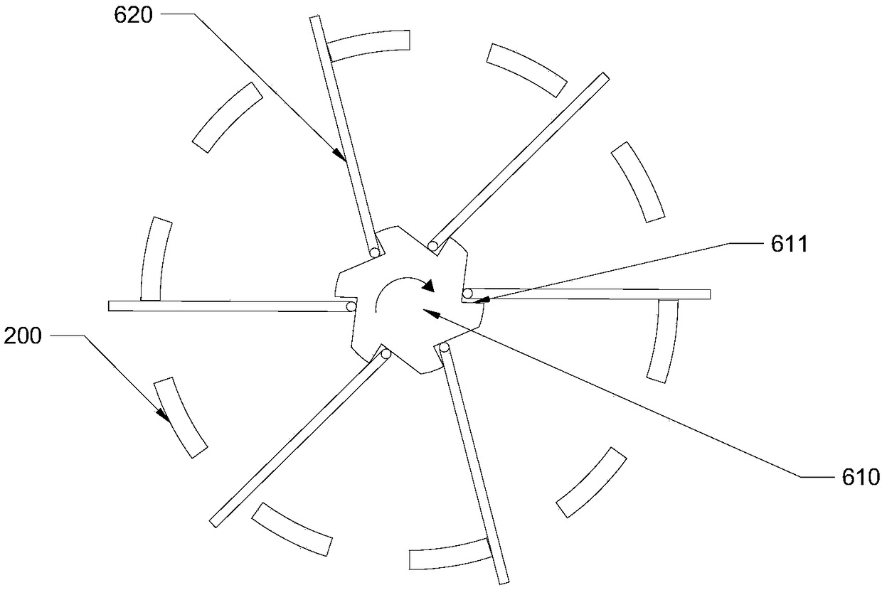
[0065] A structure of the peeling drive device is as follows: it includes a peeling motor, a peeling transmission unit, a peeling rotating shaft 610, an elastic member and a peeling rod 620, and the peeling motor drives the peeling rotating shaft 610 through the peeling transmission unit. Rotately installed in the box 100, the peeling rotating shaft 610 is coaxial with the attachment member 200, the peeling rod 620 is hinged on the peeling rotating shaft 610, and the peeling rotating shaft 610 is provided with There is a distal limit portion 611, when the peeling rod 620 abuts against the limit portion under the pressure of the elastic member, the end of the peeling rod 620 extends out of the attachment mem...
PUM
 Abstract
Description
Claims
Application Information
 - R&D
- Intellectual Property
- Life Sciences
- Materials
- Tech Scout
- Unparalleled Data Quality
- Higher Quality Content
- 60% Fewer Hallucinations
Browse by: Latest US Patents, China's latest patents, Technical Efficacy Thesaurus, Application Domain, Technology Topic, Popular Technical Reports.
© 2025 PatSnap. All rights reserved.Legal|Privacy policy|Modern Slavery Act Transparency Statement|Sitemap|About US| Contact US: help@patsnap.com


