
Hydraulic-driven reciprocating water pump used in fresh water cooling and dust removal system

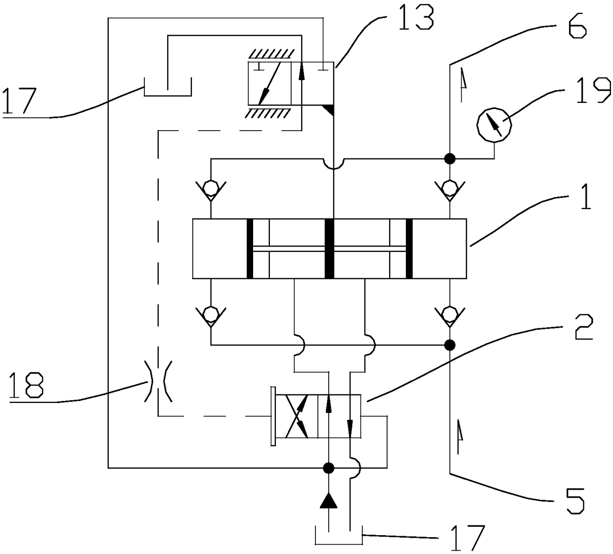
A dust removal system, reciprocating technology, applied to the parts of pumping devices for elastic fluids, variable displacement pump parts, liquid fuel engines, etc., can solve the problems of difficult processing, large hydraulic shock, poor anti-pollution ability, etc. problem, to achieve the effect of simple and reliable operation, small hydraulic shock and simple control

Pending Publication Date: 2018-09-21
HUST WUXI RES INST
View PDF6 Cites 2 Cited by
  • Summary
  • Abstract
  • Description
  • Claims
  • Application Information

AI Technical Summary

Problems solved by technology

There are axial piston pumps and reciprocating water pumps that can meet higher pressure requirements: axial piston pumps can provide higher pressure, and the pulsation impact is smaller, but axial piston pumps have more parts and higher coordination requirements , the processing is relatively difficult, the cost is relatively expensive, and the plunger pump has high requirements on the medium and poor anti-pollution ability; the reciprocating water pump has the advantages of high pumping pressure, good suction performance, high efficiency, and adaptable to a wide range of conveying media. The commonly used reciprocating water pump in the form of a motor-driven crankshaft and connecting rod frequently changes direction during work, resulting in a large hydraulic impact and troublesome direction change

Method used


Image

  • Hydraulic-driven reciprocating water pump used in fresh water cooling and dust removal system
  • Hydraulic-driven reciprocating water pump used in fresh water cooling and dust removal system
  • Hydraulic-driven reciprocating water pump used in fresh water cooling and dust removal system

Examples


Embodiment Construction

[0016] Embodiments of the present invention are described in detail below, examples of which are shown in the drawings, wherein the same or similar reference numerals designate the same or similar elements or elements having the same or similar functions throughout. The embodiments described below by referring to the figures are exemplary only for explaining the present invention and should not be construed as limiting the present invention. On the contrary, the embodiments of the present invention include all changes, modifications and equivalents coming within the spirit and scope of the appended claims.

[0017] In describing the present invention, it should be understood that the terms "center", "longitudinal", "transverse", "length", "width", "thickness", "upper", "lower", "front", " Back", "Left", "Right", "Vertical", "Horizontal", "Top", "Bottom", "Inner", "Outer", "Axial", "Radial", "Circumferential", etc. The indicated orientation or positional relationship is based ...


PUM


Abstract

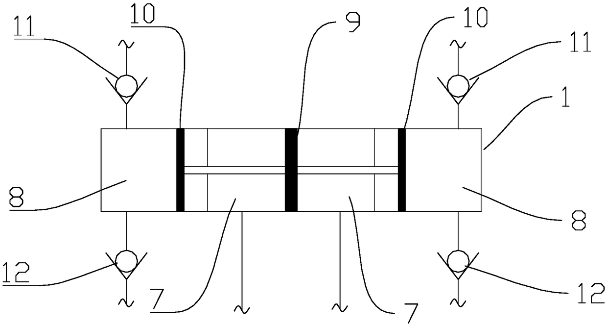
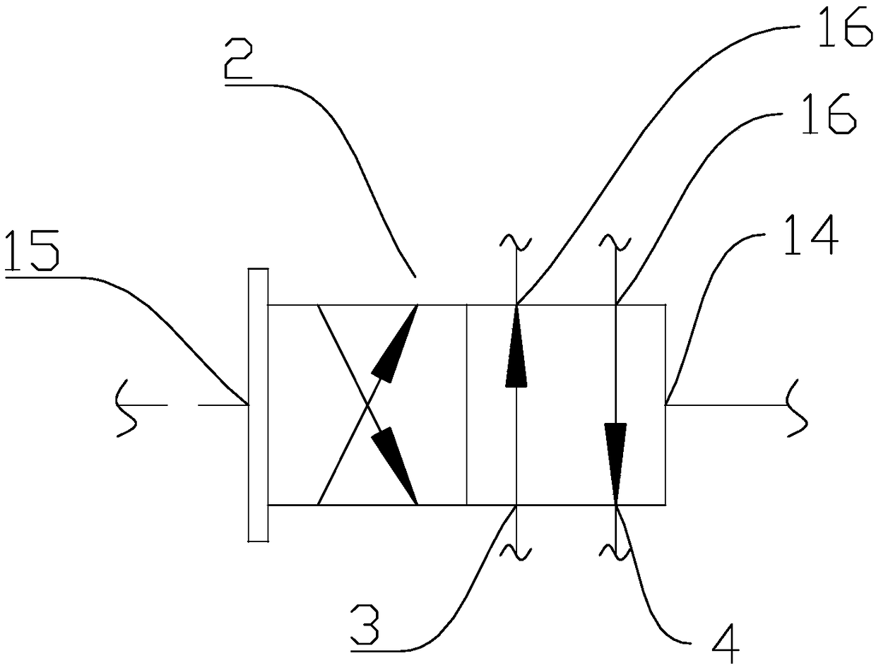
The invention provides a hydraulic-driven reciprocating water pump used in a fresh water cooling and dust removal system. The water pump comprises a water pump shell and a reversing valve, wherein thereversing valve is provided with an oil inlet, an oil return port and two working ports, a water inlet and a water outlet are formed in the water pump shell, a reversing mechanism for switching the valve core station is arranged on the reversing valve, and the inner cavity of the water pump shell is divided into an oil cavity and two water cavities which are arranged on the left side and the right side of the oil cavity respectively; an oil piston is arranged in the oil cavity, and water pistons rigidly connected with the oil piston is arranged in the two water cavities respectively; the twoworking ports communicate with the parts, at the two sides of the oil piston, of the oil cavity respectively; and the two water cavities are provided with first one-way valves communicating with the water outlet correspondingly, and the two water cavities are provided with second one-way valves communicating with the water inlet correspondingly. According to the work of the oil pressure-driven reciprocating type water pump, the hydraulic impact of pumped water flow is small, the water flow is stable, meanwhile, the water pump can be automatically reversed, control is simple, the manufacturingand maintenance cost is low, and the operation is simple and reliable.

Description

technical field [0001] The invention relates to the field of cooling and dust removal, in particular to a hydraulically driven reciprocating water pump used in a fresh water cooling and dust removal system. Background technique [0002] With the development of water systems in various fields such as dust removal, cooling, fire extinguishing, and seawater desalination, the development of water pumps, the power source in water systems, is becoming more and more diverse. There are axial piston pumps and reciprocating water pumps that can meet higher pressure requirements: axial piston pumps can provide higher pressure, and the pulsation impact is smaller, but axial piston pumps have more parts and higher coordination requirements , the processing is relatively difficult, the cost is relatively expensive, and the plunger pump has high requirements on the medium and poor anti-pollution ability; the reciprocating water pump has the advantages of high pumping pressure, good suction...

Claims


Application Information

Patent Timeline
Patent Type & Authority Applications(China)
IPC IPC(8): F04B9/115F04B49/00F04B53/10F04B53/00
CPCF04B9/115F04B49/002F04B53/00F04B53/10
Inventor 刘银水侯宝宝牛壮
Owner HUST WUXI RES INST
Learn More