Throttling window valve sleeve of main distributing valve

A throttling window and main pressure distribution valve technology, which is applied in the direction of fluid pressure actuators, servo motor components, mechanical equipment, etc., can solve problems such as hydraulic shock, reduced system control stability, and rapid oil velocity changes. Achieve the effects of reducing hydraulic shock, ensuring control accuracy and improving control stability

Active Publication Date: 2016-11-16
NANJING NARI GROUP CORP +1
View PDF4 Cites 2 Cited by
  • Summary
  • Abstract
  • Description
  • Claims
  • Application Information

AI Technical Summary

Problems solved by technology

The existing problems are: the throttling window in the form of a rectangular hole is near the neutral, fully open and fully closed positions of the main pressure distribution valve. The stability is reduced; the throttle window in the form of a circular hole has a non-linear area gradient within the full stroke range of the valve core, and it is difficult to accurately control the output of the main pressure distribution valve

Method used


Image

  • Throttling window valve sleeve of main distributing valve
  • Throttling window valve sleeve of main distributing valve
  • Throttling window valve sleeve of main distributing valve

Examples


Embodiment Construction

[0021] The technical solutions in the present invention will be clearly and completely described below in conjunction with the accompanying drawings in the embodiments of the present invention. The following examples are only used to illustrate the technical solution of the present invention more clearly, but not to limit the protection scope of the present invention.

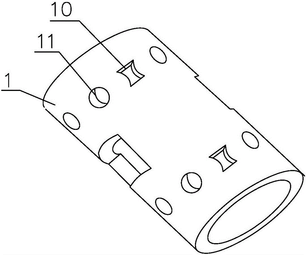
[0022] Such as figure 1 As shown, it is a throttling window sleeve of a main pressure distribution valve. A set of throttling windows is respectively provided on the upper side and the lower side of the valve sleeve 1, and each set of throttling windows includes a plurality of I-shaped holes 10 and a plurality of round The I-shaped holes 10 and circular holes 11 in each group of throttling windows are evenly arranged on the circumference of the valve sleeve 1 . Here, the I-shaped hole 10 and the circular hole 11 do not have to be spaced apart from each other, as long as the distance between the holes is equal....


PUM


Abstract

The invention discloses a throttling window valve sleeve of a main distributing valve. Two groups of throttling windows are respectively arranged on the upper and lower sides of the valve sleeve, each group of throttling window comprises a plurality of I-shaped holes and a plurality of round holes, and the I-shaped holes and the round holes in each group of throttling window are uniformly distributed in the circumference of the valve sleeve. Thus, the I-shaped holes and the round holes are not necessarily separated from each other, and only the spacing between the holes needs to be proper. The length of the I-shaped holes along the axial direction of the valve sleeve is not less than the diameters of the round holes; the upper and lower groups of throttling windows are symmetrically arranged. The cross section of each I-shaped hole is designed into an I shape enclosed by straight opposite sides and curved opposite sides, and the cross section is in axial symmetry and central symmetry. By designing the throttling windows of the valve sleeve of the main distributing valve, hydraulic shock can be reduced, and the control stability of the main distributing valve is increased.

Description

technical field [0001] The invention belongs to the technical field of hydraulic generator control, and in particular relates to a throttling window valve sleeve of a main pressure distribution valve. Background technique [0002] The main pressure distribution valve is the power level hydraulic amplifier of the mechanical hydraulic system of the turbine governor, which amplifies the mechanical displacement or hydraulic control signal of the electro-hydraulic converter into a hydraulic signal in the corresponding direction, proportional to it, and meets the flow requirements of the servomotor , to control the opening or closing of the servomotor. The main pressure distribution valve pushes the servomotor and then pushes the guide vane of the water inlet of the water turbine to realize the control of the water flow into the water turbine, so as to achieve the purpose of controlling the speed of the water turbine. [0003] The throttling window is set on the valve sleeve of t...

Claims


Application Information

Patent Timeline
Patent Type & Authority Applications(China)
IPC IPC(8): F15B13/02
CPCF15B13/02
Inventor 吴缙李建华李永红苑宝玉李悦岑刘艳平何林波王军涛
Owner NANJING NARI GROUP CORP
Why Eureka
Try Eureka