Particle dryer

A particle drying and cabinet technology, which is applied to the drying of granular materials, non-progressive dryers, dryers, etc., can solve the problems of poor drying effect of material particles, achieve enhanced drying effect, good drying effect, and improve efficiency Effect

Pending Publication Date: 2018-09-21
遵义双河生物燃料科技有限公司
View PDF1 Cites 2 Cited by
  • Summary
  • Abstract
  • Description
  • Claims
  • Application Information

AI Technical Summary

Problems solved by technology

[0005] The purpose of the present invention is to provide a particle dryer to solve the problem of poor drying effect of material particles in the prior art

Method used


Image

  • Particle dryer
  • Particle dryer

Examples


Embodiment Construction

[0022] The following is further described in detail through specific implementation methods:

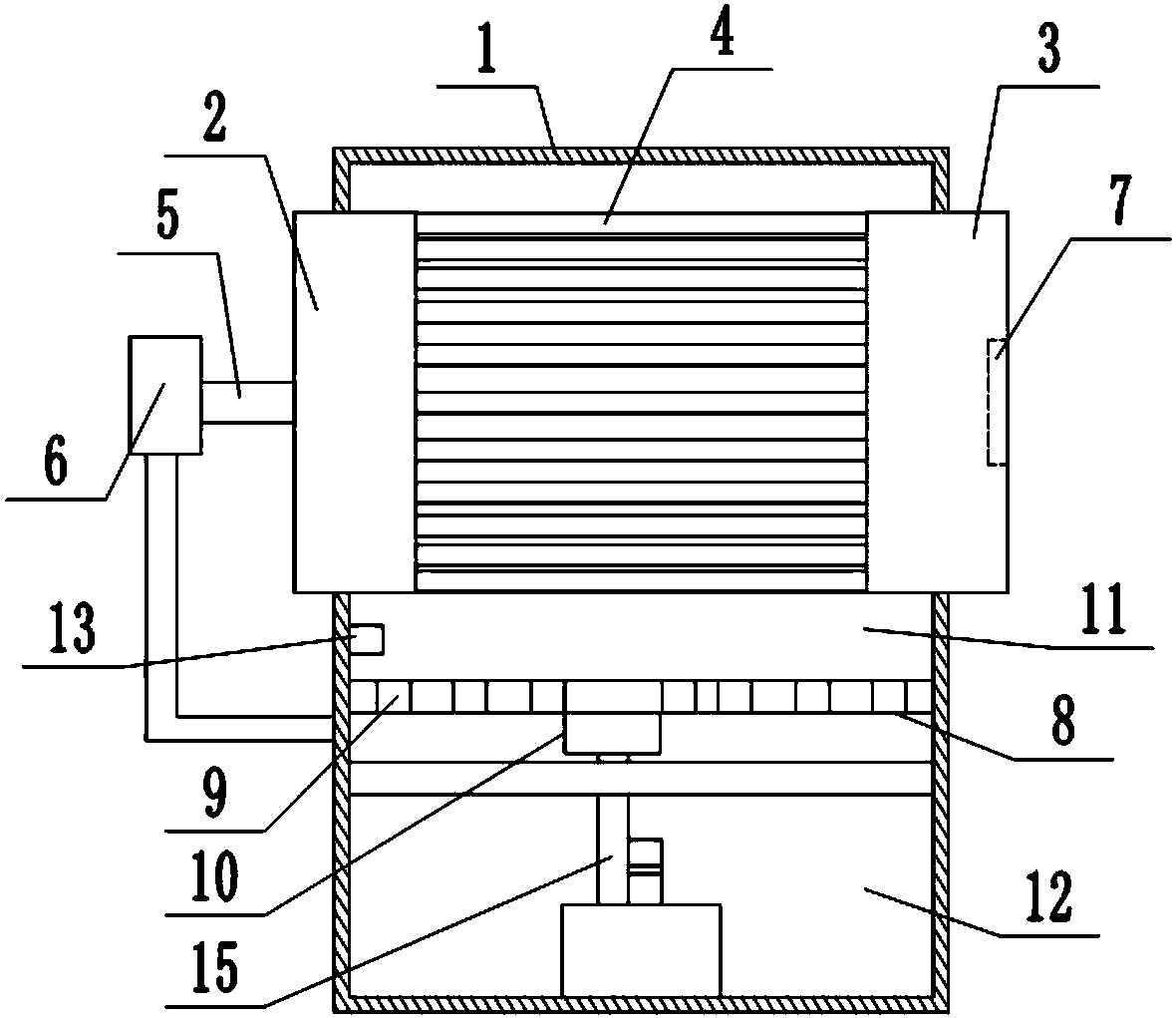
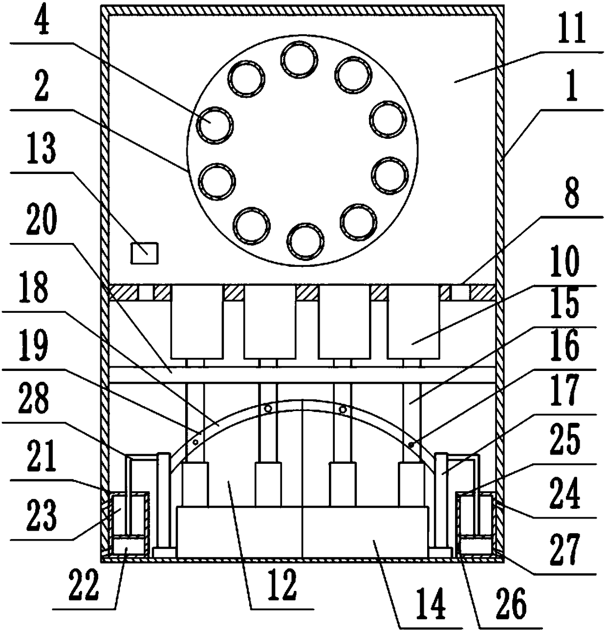
[0023] The reference signs in the drawings of the description include: box 1, turntable 2, second turntable 3, feeding pipe 4, rotating shaft 5, motor 6, negative pressure fan 7, partition plate 8, air inlet 9, connecting pipe 10, Combustion chamber 11, movable chamber 12, igniter 13, fuel supply tank 14, plunger 15, connecting column 16, cylinder 17, elastic sheet 18, chute 19, baffle plate 20, cylinder body 21, suction part 22, air supply Part 23, first air inlet 24, first air outlet 25, second air inlet 26, second air outlet 27, connecting rod 28.

[0024] The embodiment is basically as attached figure 1 And attached figure 2 Shown:

[0025] The particle dryer is mainly composed of a box body 1, a feeding mechanism, an elastic sheet 18, a fuel pipe, a connecting pipe 10, a cylinder 17, a cylinder body 21, and a plunger 15. The outside of the box body 1 is provided with a heat...


PUM


Abstract

The invention relates to the field of bio-fuels and discloses a particle dryer. The particle dryer comprises a box body, wherein a partition plate divides the box body into a combustion cavity and a movement cavity; an igniter is arranged in the combustion cavity; a feeding mechanism is arranged on the combustion cavity; a fuel supply box is arranged in the movement cavity; a plurality of fuel pipes are communicated with the top of the fuel supply box; a plunger is connected to the interior of each fuel pipe in a sliding manner; the tops of the plungers are connected to the interiors of connecting pipes in a sliding manner; a one-way valve is arranged in each plunger; connecting posts are fixed at the parts, exposed between the connecting pipes and the fuel pipes, of the plungers; a cylinder is arranged on each of two sides of the fuel supply box, output ends of the two cylinders are connected to an elastic sheet, and a plurality of chutes allowing the connecting posts to slide thereinare formed in the elastic sheet; and a baffle is fixed in the movement cavity, and the elastic sheet can be propped against the baffle in a moving process. According to the scheme, material particlescan be dried in the movement process, a heating mode is improved with reference to the characteristics of a feeding mechanism, the drying efficiency of the material particles is greatly improved, andthe drying effect is enhanced.

Description

technical field [0001] The invention belongs to the field of biofuels. Background technique [0002] Biofuel needs to be dried after being extruded to form material particles. The traditional drying method is to put the material particles into a drying box for stirring, so that the material particles are in contact with hot air to achieve drying. [0003] The Chinese patent document with the publication number CN107189835A discloses a production equipment for biomass fuel, which includes a stirring mechanism, a drying mechanism and a granulation mechanism connected in sequence. The stirring mechanism includes a stirring box, and a stirring shaft is arranged in the stirring box. There are multiple shaft sleeves on the top, the outer side of the shaft sleeve is fixed with a stirring rod, and the upper end of the stirring shaft is fixed with a stirring motor; the upper left end of the stirring mechanism is provided with a feeding chute, and the entrance of the feeding chute is ...

Claims


Application Information

Patent Timeline
Patent Type & Authority Applications(China)
IPC IPC(8): F26B11/04F26B23/02F26B25/16F26B25/12
CPCF26B11/04F26B23/02F26B25/12F26B25/16F26B2200/08
Inventor 刘福基
Owner 遵义双河生物燃料科技有限公司
Why Eureka
Try Eureka