Column re-attachment demolding device

A demoulding device and post-planting technology, which is applied to the assembly of printed circuits with electrical components, electrical components, and printed circuit manufacturing. It can solve problems such as damage to ceramic bodies, cracking of solder joints, and difficulty in separating molds from CLGA.

Inactive Publication Date: 2018-09-21
CHANGCHUN INST OF OPTICS FINE MECHANICS & PHYSICS CHINESE ACAD OF SCI
View PDF4 Cites 1 Cited by
  • Summary
  • Abstract
  • Description
  • Claims
  • Application Information

AI Technical Summary

Problems solved by technology

[0004] Due to the surface tension of the molten solder, the high lead post will be slightly inclined, and finally maintain this state under the limitation of the mold array hole. Get out of trouble
Improper demolding methods will cause fatigue damage, fracture, solder joint cracking or damage to the ceramic body of the high lead post, resulting in failure of the planting post

Method used


Image

  • Column re-attachment demolding device
  • Column re-attachment demolding device
  • Column re-attachment demolding device

Examples


Embodiment Construction

[0031] In order to make the practical purpose, technical implementation, and program advantages of the patent of the present invention clearer, the specific implementation of the patent will be detailed according to the drawings of the patent of the invention. In the drawings, the described embodiments are part of the embodiments of the present invention, rather than all of the embodiments. The embodiments described in the drawings are exemplary and are intended to explain the present invention, but should not be construed as limiting the present invention. Based on this embodiment, all other embodiments obtained by a person of ordinary skill in the art without creative work shall fall within the protection scope of the present invention. This embodiment will be described in detail below in conjunction with the drawings.

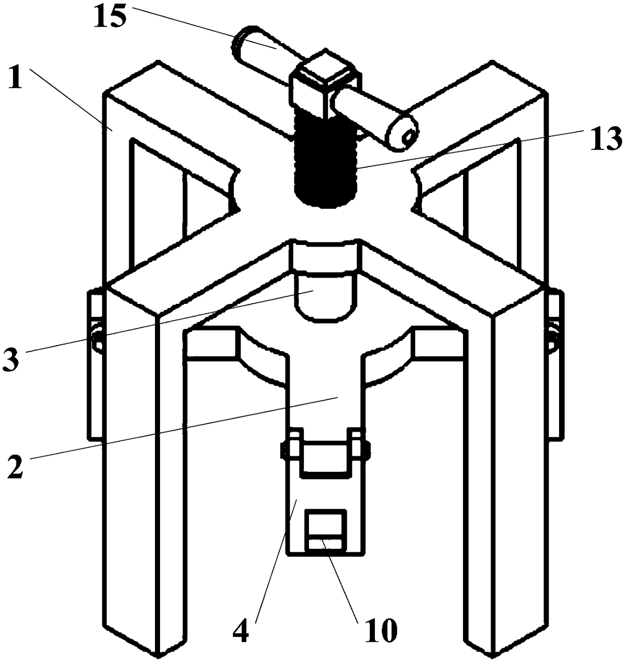
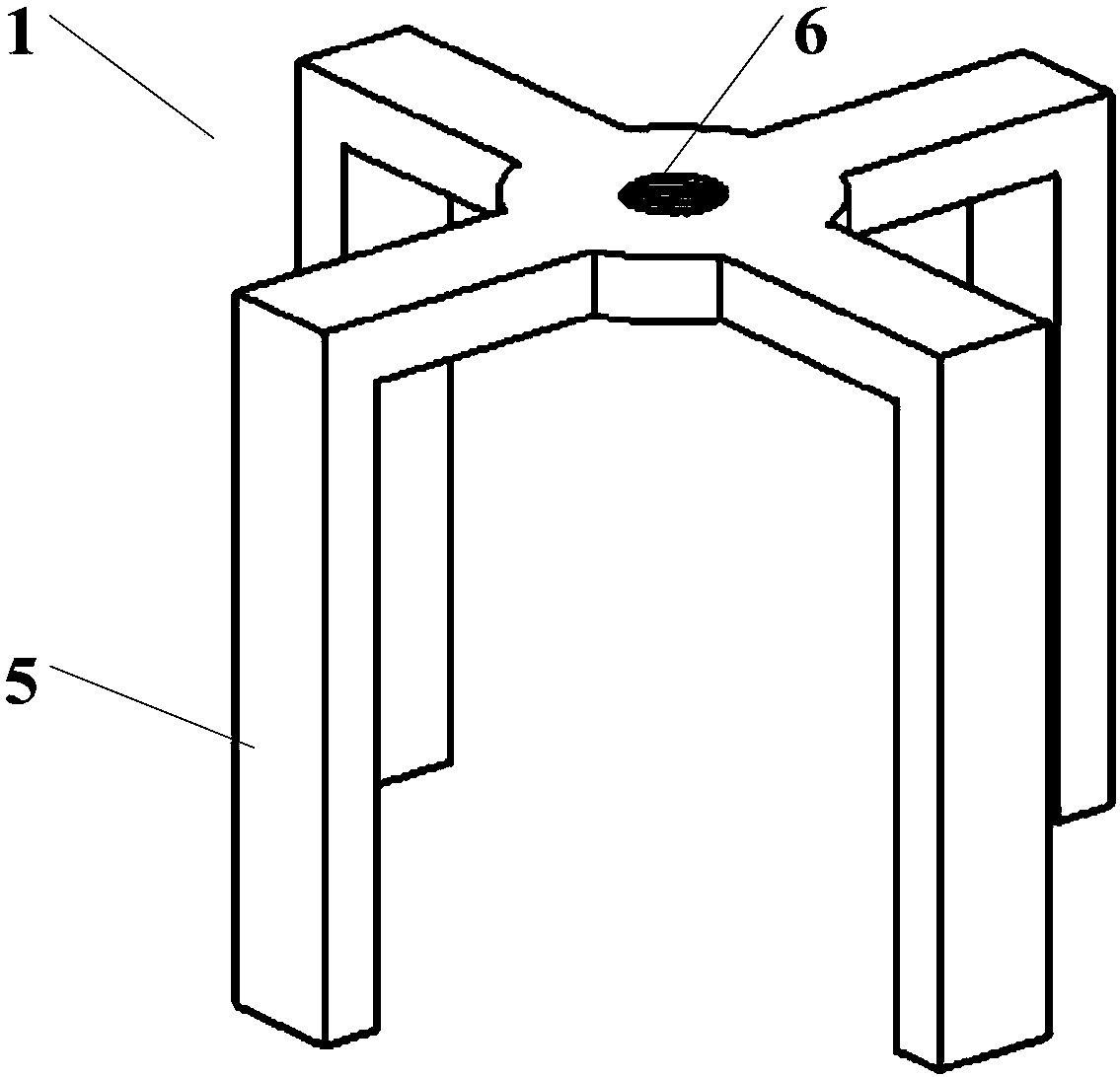
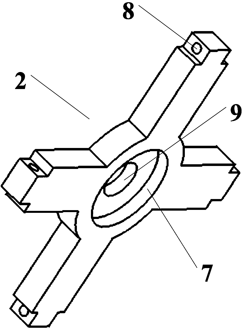
[0032] See Figure 1 to Figure 7 , The present invention provides a planting column demoulding device, including an outer support frame (1), an inner support...


PUM


Abstract

The invention provides a column re-attachment demolding device. The column re-attachment demolding device comprises an outer supporting frame (1), an inner supporting frame (2), a transmission mechanism (3) and hangers (4). The inner supporting frame (2) is embedded into the outer supporting frame (1), and the inner supporting frame (2) is connected with the outer supporting frame (1) through thetransmission mechanism (3). The inner supporting frame (2) comprises multiple cross columns, the cross columns are horizontally arranged and arrayed, and the included angle between every two adjacentcross columns is identical. The hangers (4) are arranged at the ends of the cross columns, each cross column is correspondingly provided with one hanger (4), and the hangers (4) and the ends of the cross columns are detachably locked. The transmission mechanism (3) is used for driving the inner supporting frame (2) and the hangers (4) to rise or fall in the vertical direction. By means of the device, it can be guaranteed that in the demolding process, a packaging device is evenly stressed, the demolding quality after column re-attachment is improved, and the success rate after column re-attachment is increased.

Description

Technical field [0001] The invention relates to the technical field of electronic packaging, in particular to an auxiliary device used for demolding treatment after a CLGA column is planted. Background technique [0002] CLGA (Ceramic Land Grid Array) is the English abbreviation of grid array package. The ceramic ball grid array (CBGA) or ceramic column grid array (CCGA) package can be obtained by planting balls or pillars on the surface of the arrayed pads Device. This type of device has very high reliability, especially the CCGA packaged device can effectively offset the thermal stress induced by the mismatch of the thermal expansion coefficient between the component body and the printed circuit board, so it is used in high-reliability electronic products such as aerospace Can be widely used. [0003] CLGA needs high-lead pillars to realize the electrical and structural connection between the ceramic body and the printed circuit board. The process of planting the pillars is as...

Claims


Application Information

Patent Timeline
Patent Type & Authority Applications(China)
IPC IPC(8): H05K3/34
CPCH05K3/34H05K2203/1305
Inventor 张艳鹏王威王玉龙
Owner CHANGCHUN INST OF OPTICS FINE MECHANICS & PHYSICS CHINESE ACAD OF SCI
Why Eureka
Try Eureka