Prism mounting device

A technology for installing devices and prisms, applied in installation, optics, instruments, etc., can solve the problems of poor imaging effects of instruments, data errors, increased processing difficulty and production costs of prisms and related accessories, and ensure product imaging effects and Corresponding data accuracy, improved position accuracy, precise and fast adjustment effect

Pending Publication Date: 2018-09-25
CHANGCHUN YUHENG TIMES OPTOELECTRONICS TECHCO
View PDF0 Cites 1 Cited by
  • Summary
  • Abstract
  • Description
  • Claims
  • Application Information

AI Technical Summary

Problems solved by technology

[0002] In the prior art, prisms are used as spectroscopic elements in some spectroscopic instruments to split light. Therefore, the installation of prisms is particularly important. The installation position of prisms is accurate and stable, which can make the imaging of the instrument clear and of good quality, which is beneficial to spectral analysis. If the installation position of the prism is inaccurate and the imaging effect of the instrument is not good, it will cause a large error to the data obtained by spectral analysis, which will seriously affect the accuracy of the analysis results.
[0003] In the current existing prism installation technology, the prism is usually directly fixed and installed on the prism chassis, but this assembly and installation structure only plays a role in fixing the prism, and the accuracy of the installation position of the prism depends entirely on the prism, the prism chassis and the The processing accuracy of some related mechanical parts is guaranteed, which undoubtedly increases the processing difficulty and production cost of prisms and related accessories, and if the processing accuracy of prisms and related accessories cannot be guaranteed, it will directly affect the imaging effect of spectral analysis instruments and data error

Method used


Image

  • Prism mounting device
  • Prism mounting device

Examples


Embodiment Construction

[0022] The core of the present invention is to provide a prism installation device, which can accurately and reliably install the prism, so as to improve the product imaging effect and data accuracy of the spectroscopic instrument.

[0023] In order to enable those skilled in the art to better understand the solution of the present invention, the present invention will be further described in detail below in conjunction with the accompanying drawings and specific embodiments.

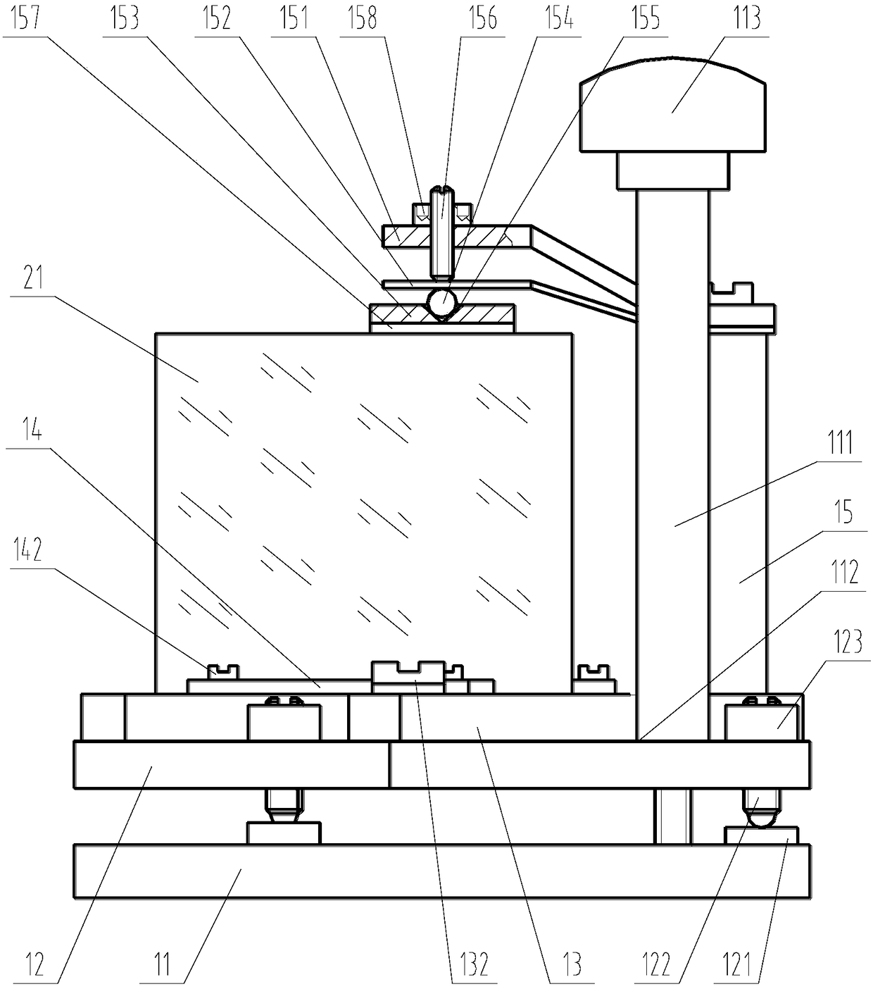
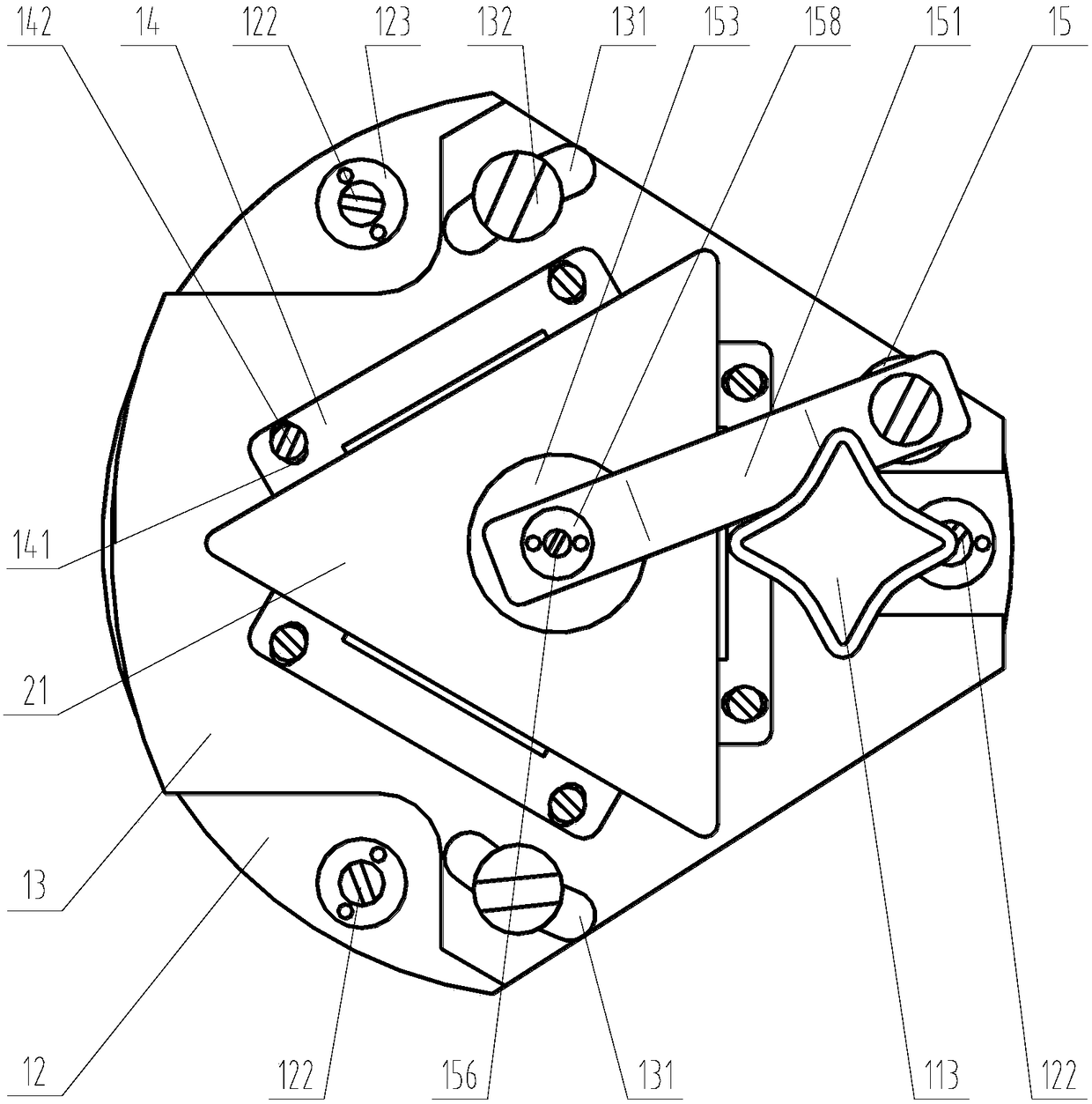
[0024] Please refer to figure 1 with figure 2 , figure 1 A structural front view of a prism mounting device provided for a specific embodiment of the present invention; figure 2 for figure 1 top view.

[0025] In a specific embodiment, the prism mounting device provided by the present invention includes a base 11 and a locking pin 111, the base 11 is provided with a chassis 12, and the bottom end of the locking pin 111 penetrates the chassis 12 from top to bottom and is connected with The base 11...


PUM


Abstract

The invention discloses a prism mounting device. A chassis is arranged on a base; a bottom end of a locking pin penetrates the chassis from top to bottom and form a thread fit with the base; a limiting member pressing against a top surface of the chassis is arranged on the locking pin; a plurality of longitudinal adjustment devices are arranged between the base and the chassis; a tray is arrangedon the chassis; positioning blocks which are pressed against a prism in the circumference direction are arranged on the tray; a vertical column is arranged on one side of the tray; a pressing plate and a spring plate which are opposite to each other are successively arranged on the top of the vertical column from top to bottom; a free end of the pressing plate and a free end of the spring plate are positioned above the prism; a pressing plate seat is arranged under the spring plate; a steel ball is arranged between the pressing plate seat and the spring plate; a limiting holding structure matching the steel ball is arranged on the top of the pressing plate seat; and a locking nail which forms a thread fit with the pressing plate and is pressed against the spring plate penetrates the pressing plate in the vertical direction. The prism mounting device can accurately and reliably mounts the prism so as to improve the product imaging effect and the data accuracy of the spectrometer.

Description

technical field [0001] The invention relates to the technical field of optical matching components of spectrometers, in particular to a prism installation device. Background technique [0002] In the prior art, prisms are used as spectroscopic elements in some spectroscopic instruments to split light. Therefore, the installation of prisms is particularly important. The installation position of prisms is accurate and stable, which can make the imaging of the instrument clear and of good quality, which is beneficial to spectral analysis. If the installation position of the prism is inaccurate, resulting in poor imaging effect of the instrument, it will cause a large error in the data obtained by spectral analysis, which will seriously affect the accuracy of the analysis results. [0003] In the current existing prism installation technology, the prism is usually directly fixed and installed on the prism chassis, but this assembly and installation structure only plays a role in...

Claims


Application Information

Patent Timeline
Patent Type & Authority Applications(China)
IPC IPC(8): G02B7/18
CPCG02B7/1805
Inventor 侯玉飞武平尤欣季文超
Owner CHANGCHUN YUHENG TIMES OPTOELECTRONICS TECHCO
Why Eureka
Try Eureka