Adaptive tuning device and tuning method of emission end of wireless electric power transmission device

A technology of wireless power transmission and tuning device, applied in circuit devices, electrical components, etc., can solve the problems of poor continuity of discrete array capacitor adjustment, inability to guarantee system resonance state, and no practicability, and achieve easy promotion and increase in size. , the effect of not easy to carry

Inactive Publication Date: 2018-09-25
CHONGQING UNIV OF POSTS & TELECOMM
View PDF5 Cites 20 Cited by
  • Summary
  • Abstract
  • Description
  • Claims
  • Application Information

AI Technical Summary

Problems solved by technology

Since there will be some errors in manual adjustment, the system cannot be guaranteed to work in a resonance state, the transmission efficiency is low, and the system is not practical; the discrete array capacitor adjustment has poor continuity, poor adjustment accuracy and high cost, which is not conducive to implementation. How to realize the transmission device according to the reception The resonant frequency of the terminal is different, and the resonant frequency of itself is automatically adjusted, and it has the performance of fast response, high precision and good stability, which is an urgent problem to be solved.

Method used


Image

  • Adaptive tuning device and tuning method of emission end of wireless electric power transmission device
  • Adaptive tuning device and tuning method of emission end of wireless electric power transmission device
  • Adaptive tuning device and tuning method of emission end of wireless electric power transmission device

Examples


Embodiment Construction

[0028] The present invention will be further described below in conjunction with accompanying drawing.

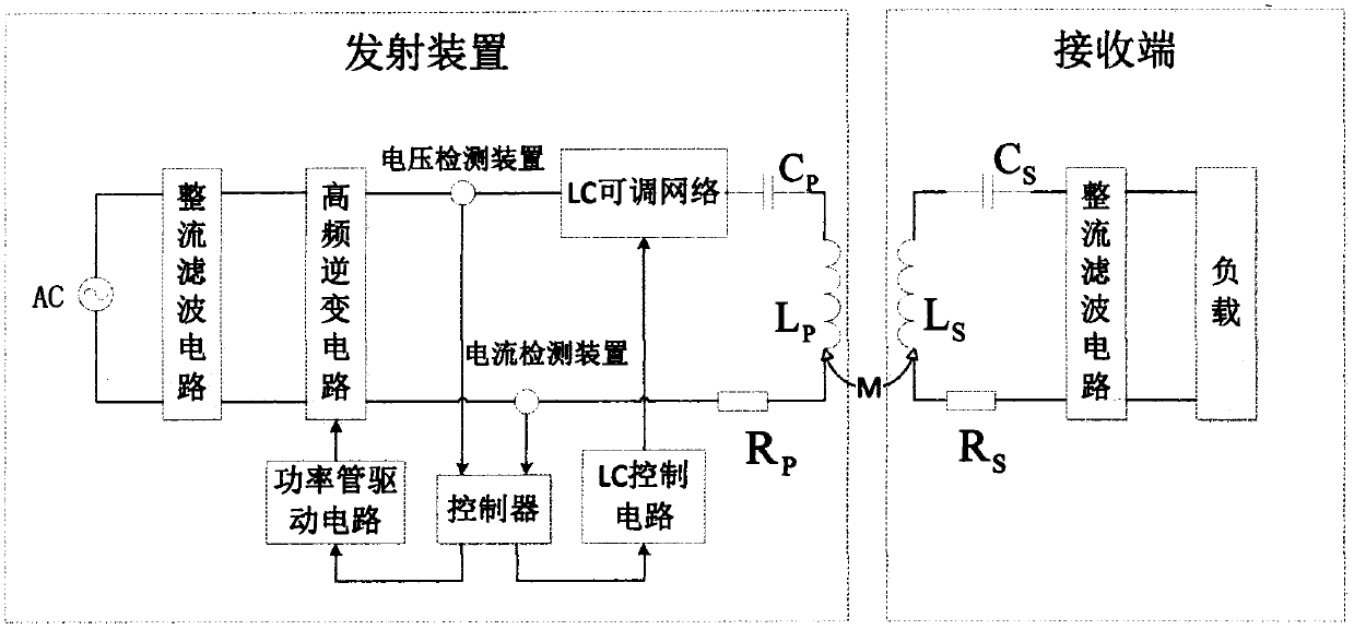
[0029] Such as figure 1 As shown, a specific embodiment of the present invention is an adaptive tuning device for a transmitting end of a wireless power transmission device, which is characterized in that:

[0030] The transmitting device can transmit energy with the receiving end through magnetic field coupling resonance. The device consists of an AC power supply, a rectifier filter circuit, a high-frequency inverter circuit, a voltage detection device, an LC adjustable network, and a compensation capacitor C P , Transmitting coil L P , Transmitter impedance R P The current detection devices are electrically connected in turn, and the rectification circuit converts the low-frequency alternating current into direct current, and then further converts it into high-frequency alternating current through the high-frequency inverter circuit to the transmitting coil. The curren...


PUM


Abstract

The invention provides an adaptive tuning device and tuning method of emission end of a wireless electric power transmission device. An alternating current power supply, a rectification filtering circuit, a high-frequency inversion circuit, a voltage detection device, an LC adjustable network, a compensation capacitor CP, an emission coil LP, an emission end impedance RP and a current detection device are successively connected together. A controller receives current and output of the current detection device and calculates and controls the high-frequency inversion circuit and the LC adjustable network. Two full-controlled devices M1 and M2 are serially connected with diodes D1 and D2, then are reversely parallelly connected with each, then are serially connected with a fixed inductor LT and then are parallelly connected with a power common capacitor CT, so a phase-controlled inductor capacitor parallel circuit is formed. S1 and S2 are square waves for the LC control circuit to controlon and off the M1 and M2. According to the invention, stability of the energy transmission system can be improved; and defects that the current wireless energy transmission system is easily detuned and an emission device fails to transmit energy to various kinds of receiving ends are solved.

Description

technical field [0001] The invention belongs to the field of wireless energy transmission technology and novel energy conversion technology, and in particular relates to an adaptive tuning device and a tuning method for a magnetic coupling resonance type wireless power transmission equipment. Background technique [0002] Wireless energy transmission, that is, the transmission method in which electrical equipment can obtain electrical energy from the grid in a non-contact manner. The current wireless energy transmission methods are mainly transmission methods based on electromagnetic radiation, transmission methods based on electromagnetic induction principles, and transmission methods based on magnetic coupling resonance. Based on the magnetic coupling resonance method, two resonators with the same resonant frequency use the magnetic field as the medium to realize energy transmission. The transmission distance is at the meter level, and the system has little influence on th...

Claims


Application Information

Patent Timeline
Patent Type & Authority Applications(China)
IPC IPC(8): H02J50/12
CPCH02J5/005
Inventor 禄盛冯攀邓聪颖陈翔朴昌浩
Owner CHONGQING UNIV OF POSTS & TELECOMM
Why Eureka
Try Eureka