Waterproof spindle box for machine tool

A waterproof and spindle box technology, which is applied in the direction of metal processing machinery parts, large fixed members, metal processing equipment, etc., can solve the problems of water infiltration into the spindle box, spindle and other mechanism corrosion, so as to improve the bearing capacity, reduce raw materials, reduce The effect of the use of molten metal

Pending Publication Date: 2018-09-28
CHONGQING HONGGANG CNC MACHINE TOOL
View PDF0 Cites 0 Cited by
  • Summary
  • Abstract
  • Description
  • Claims
  • Application Information

AI Technical Summary

Problems solved by technology

[0004] The invention provides a waterproof spindle box for machine tools to solve the problem that water will seep into the spindle box in the existing spindle box, thereby causing corrosion to the spindle and other mechanisms

Method used


Image

  • Waterproof spindle box for machine tool
  • Waterproof spindle box for machine tool
  • Waterproof spindle box for machine tool

Examples


Embodiment 1

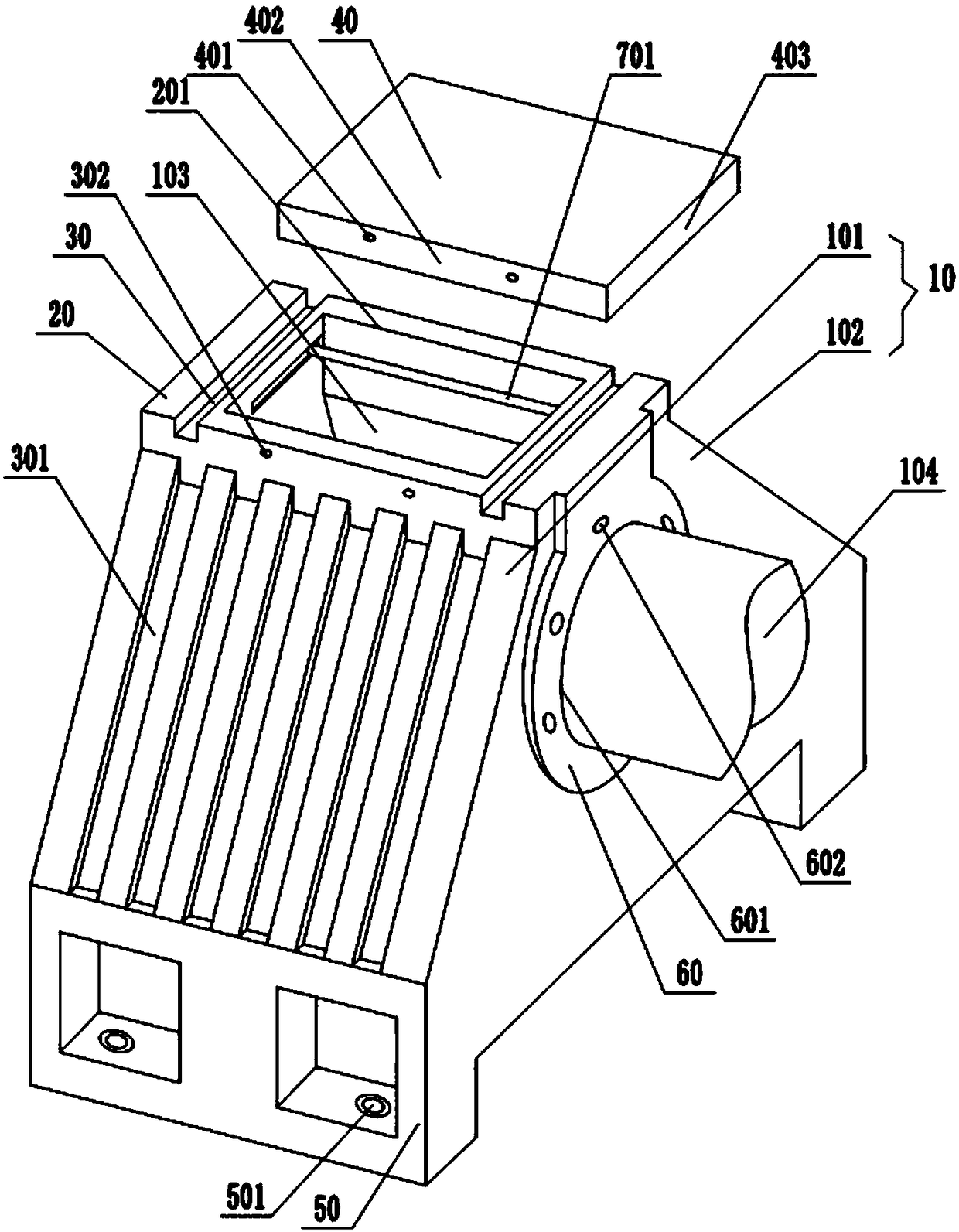
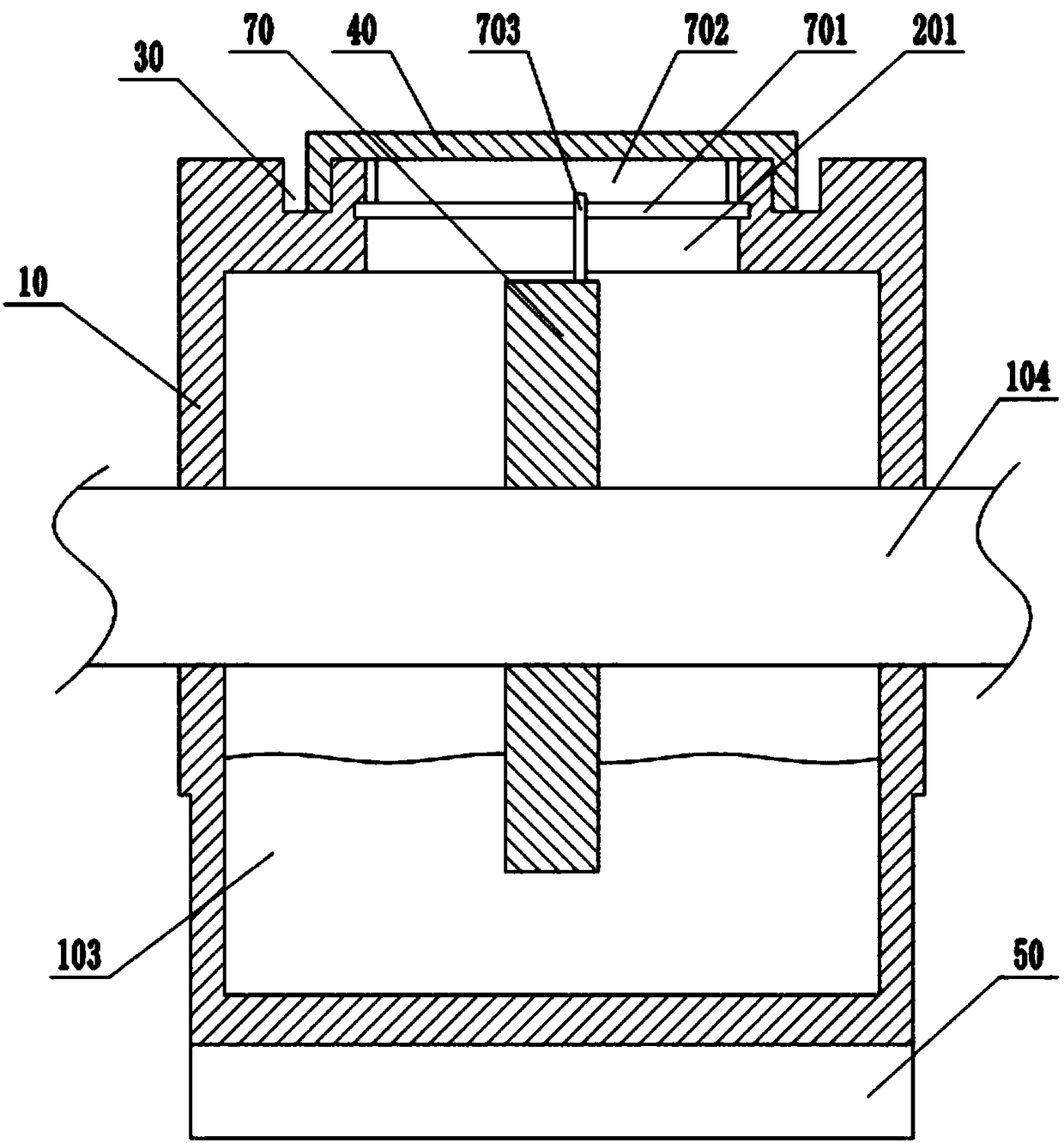
[0031] Embodiment one is basically as figure 1 and figure 2 Shown:

[0032] A waterproof headstock for machine tools, comprising a box body 10, wherein the longitudinal section of the box body 10 is a trapezoid with a narrow top and a wide bottom. The box body 10 includes two inclined surfaces 101 and two vertical surfaces 102. The top is provided with a rectangular boss 20, and a main shaft cavity 103 is provided in the box body 10, and a main shaft 104 is installed in the main shaft cavity 103, and a bearing is fixed between the main shaft 104 and the box body 10. There is an inspection hole 201 communicating with the main shaft cavity 103, wherein the inspection hole 201 is a rectangular hole.

[0033] On the rectangular boss 20, there are grooves 30 located on both sides of the inspection hole 201. On the side wall of the table 20, a plurality of diversion grooves 301 are vertically provided on the two slopes 101 of the box body 10, and the upper ends of the diversion ...

Embodiment 2

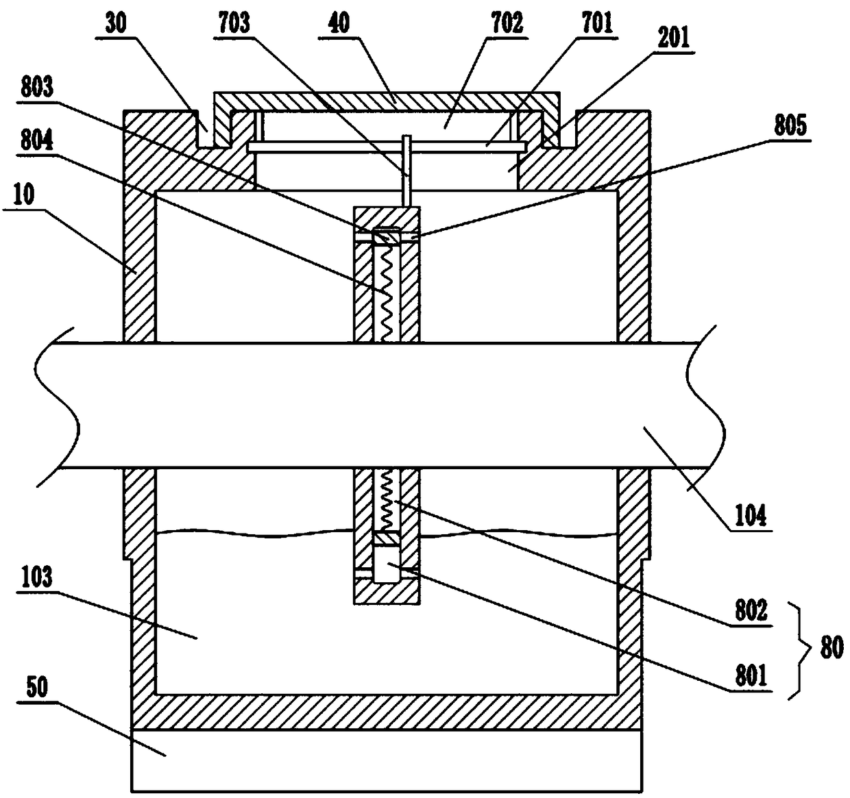
[0039] Embodiment two is basically as image 3 Shown:

[0040] The difference from Embodiment 1 is that a plurality of closed sliding chambers 80 are arranged in the oil throwing pan 70, each sliding chamber 80 is distributed around the circumference of the oil throwing pan 70, and magnetic sliding chambers 80 are slidably and sealingly connected to each other. Block 803, the sliding block 803 divides the sliding chamber 80 into an oil chamber 801 and a cavity 802, wherein the cavity 802 is close to the side of the main shaft 104, wherein the sliding block 803 is located between the side of the cavity 802 and the main shaft 104, and a second spring is fixed 804, oil holes 805 communicating with the oil chamber 801 are opened on the left and right end surfaces of the oil flinger 70. In addition, in this embodiment, the horizontal rod 701 has magnetism, and the magnetism on the opposite side of the slider 803 is opposite.

[0041] When the oil thrower 70 rotates and is immersed...


PUM


Abstract

The invention relates to the technical field of spindle boxes, in particular to a waterproof spindle box for a machine tool. The waterproof spindle box for the machine tool comprises a box body, wherein a spindle cavity is formed in the box body; a spindle is mounted in the spindle cavity; a manhole is formed in the top surface of the box body; grooves are symmetrically formed in the two sides ofthe manhole and are through grooves; a top cover is arranged above the manhole; first baffles are arranged on the two sides of the top cover, and the inner walls of the first baffles are attached to the outer wall of the box body; second baffles are arranged on the two sides of the top cover and located in the grooves; an oil throwing disc is arranged on the spindle; a horizontal rod is horizontally and glidingly connected onto the wall of the manhole; a first spring is fixed between the horizontal rod and the side wall of the manhole; wedged bars are fixed on the outer periphery of the oil throwing disc; a sponge brush is stuck on the top surface of the horizontal rod. According to the scheme, the problem that water can permeate into the box body in the prior art is solved, water is prevented from being subjected to electrochemical reactions with mechanisms such as the spindle and the like, so that corrosion to the spindle due to water is avoided, and the service life of the mechanisms such as the spindle and the like is prolonged.

Description

technical field [0001] The invention relates to the technical field of spindle boxes, in particular to a waterproof spindle box for machine tools. Background technique [0002] The spindle box is an important part of the machine tool, which is used to arrange the working spindle of the machine tool and its transmission parts and corresponding additional mechanisms. The headstock is a complex transmission part, including the main shaft assembly, reversing mechanism, transmission mechanism, braking device, operating mechanism and lubrication device, etc. Its main function is to support the main shaft and make it rotate, so as to realize the functions of main shaft starting, braking, speed changing and reversing. [0003] The box of the spindle box provides the overall support for the above-mentioned mechanism. In order to facilitate maintenance, an inspection hole is usually opened on the top surface of the spindle box box. , so there is also a flat plate on the inspection h...

Claims


Application Information

Patent Timeline
Patent Type & Authority Applications(China)
IPC IPC(8): B23B19/00
CPCB23Q1/70
Inventor 汪传宏
Owner CHONGQING HONGGANG CNC MACHINE TOOL
Why Eureka
Try Eureka