
Single-blade milling cutter

A milling cutter and cutter body technology, applied in the field of single-edged milling cutters, can solve the problems of poor surface roughness, affect performance, poor chip removal, etc., so as to solve the burr on the edge of the machined plate, improve the performance, and improve the service life. Effect

Pending Publication Date: 2018-09-28
SHENZHEN JINZHOU PRECISION TECH
View PDF0 Cites 4 Cited by
  • Summary
  • Abstract
  • Description
  • Claims
  • Application Information

AI Technical Summary

Problems solved by technology

[0002] At present, the PCB industry usually uses double-edged and multi-edged milling cutters to process flexible boards, flexible boards, PTFE, PP sheets and other soft board materials. Due to the limitation of the chip removal space and the sharpness of the cutting edge, chip removal is easy to occur during processing. Bad problems, resulting in poor roughness of the processed surface, and the phenomenon of knife breaking, and also the problem of board edge burrs, which affects the performance

Method used


Image

  • Single-blade milling cutter
  • Single-blade milling cutter
  • Single-blade milling cutter

Examples


Embodiment Construction

[0022] In order to make the objectives, technical solutions and advantages of the present invention clearer, the present invention will be further described in detail below with reference to the accompanying drawings and embodiments. It should be understood that the specific embodiments described herein are only used to explain the present invention, but not to limit the present invention.

[0023] It should be noted that when an element is referred to as being "fixed to" or "disposed to" another element, it can be directly on the other element or intervening elements may also be present. When an element is referred to as being "connected to" another element, it can be directly connected to the other element or intervening elements may also be present.

[0024] It should also be noted that the azimuth terms such as left, right, upper and lower in the embodiments of the present invention are only relative concepts to each other or refer to the normal use state of the product, a...


PUM


Abstract

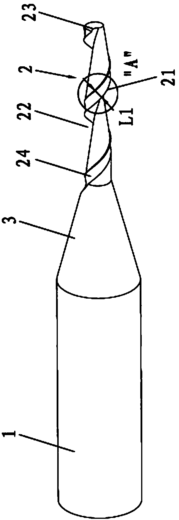
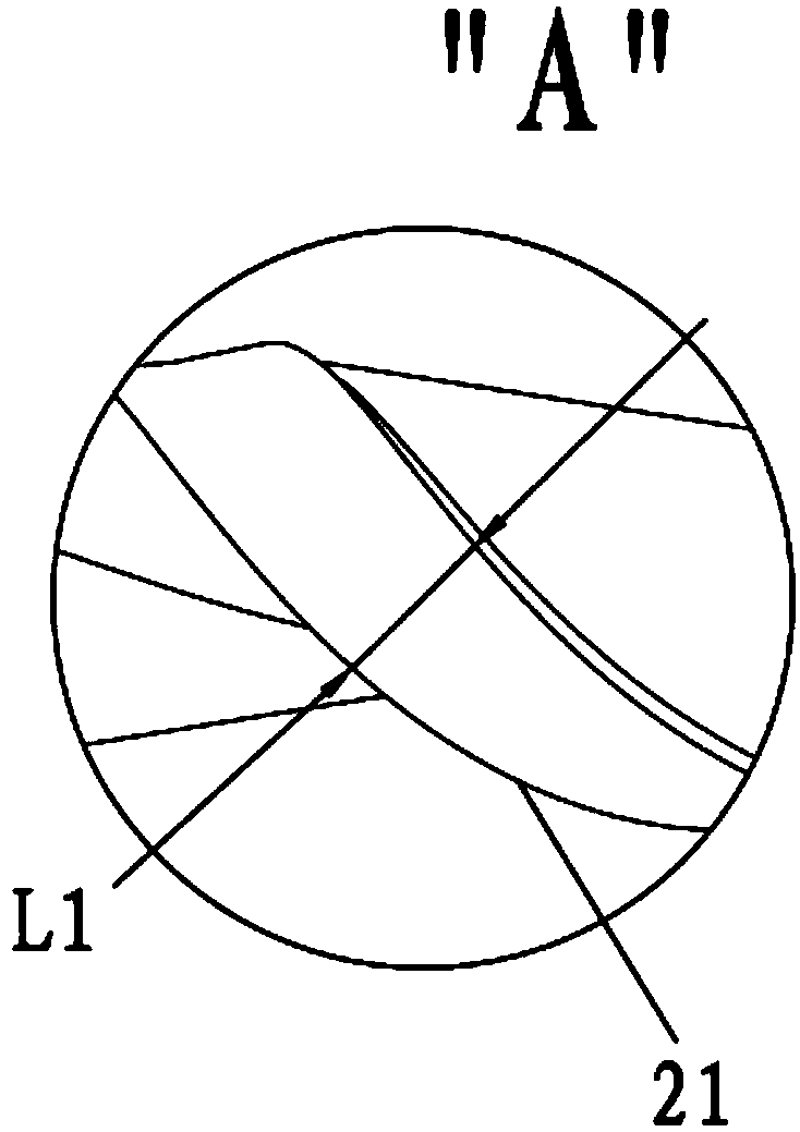
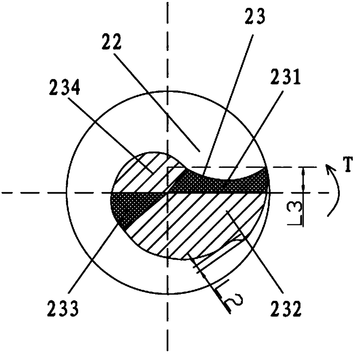
The invention discloses a single-blade milling cutter applicable to the technical field of milling cutter structures. The single-blade milling cutter comprises a cutter handle and a cutter body connected to one end of the cutter handle. The cutter body is provided with a spiral cutting blade, a chip discharging groove and a main cutting blade. The chip discharging groove and the spiral cutting blade are spirally arranged around the axis of the cutter body in the direction from the front end of the cutter body to the cutter handle. The spiral cutting blade and the chip discharging groove are same in the spiral angle. The main cutting blade is arranged at the front end of the cutter body and is adjacent to the chip discharging groove. The cutting edge of the main cutting blade is of an arc concave structure, and the main cutting edge is provided with an arc-shaped relief angle. Through the single-blade milling cutter provided by the invention, the overall stiffness strength of the milling cutter and the sharpness of the cutting edges can be improved, and meanwhile, the effect that chips are discharged smoothly is ensured.

Description

technical field [0001] The invention belongs to the technical field of milling cutter structures, in particular to a single-edged milling cutter. Background technique [0002] At present, the PCB industry usually uses double-edged and multi-edged milling cutters to process flexible board materials such as flexible boards, flexible boards, PTFE, and PP sheets. Due to the limitation of chip removal space and the sharpness of cutting edges, chip removal is easy to occur during processing. Bad problem, resulting in poor surface roughness, as well as the phenomenon of knife breakage, and the problem of burrs on the edge of the board, which affects the performance. SUMMARY OF THE INVENTION [0003] The purpose of the present invention is to overcome the above-mentioned deficiencies of the prior art, and provide a single-edged milling cutter, which can improve the overall rigidity of the milling cutter and the sharpness of the cutting edge, while ensuring the smooth discharge of ...

Claims


Application Information

Patent Timeline
Patent Type & Authority Applications(China)
IPC IPC(8): B23C5/10
CPCB23C5/10
Inventor 刘洋张辉王磊
Owner SHENZHEN JINZHOU PRECISION TECH
Learn More