Steel pipe, raw materials and manufacturing method thereof, and drill rod for rotary drilling rig

A production method and technology of steel pipes, which are applied in the direction of drill pipes, earthwork drilling, drilling pipes, etc., can solve the problems of low yield strength of steel pipes, and achieve the effects of improving yield strength, increasing hardenability, and good welding performance

Inactive Publication Date: 2018-09-28
衡阳华菱连轧管有限公司
View PDF6 Cites 2 Cited by
  • Summary
  • Abstract
  • Description
  • Claims
  • Application Information

AI Technical Summary

Problems solved by technology

[0006] The main purpose of this application is to provide a steel pipe, its raw material, its production method and drill pipe for rotary drilling rigs, so as to solve the problem of low yield strength of steel pipes in the prior art

Method used


Image

  • Steel pipe, raw materials and manufacturing method thereof, and drill rod for rotary drilling rig
  • Steel pipe, raw materials and manufacturing method thereof, and drill rod for rotary drilling rig
  • Steel pipe, raw materials and manufacturing method thereof, and drill rod for rotary drilling rig

Examples


Embodiment 1

[0045] In terms of weight percentage, the raw materials of the steel pipe include 0.33% C, 0.50% Si, 1.30% Mn, 0.020% P, 0.015% S, 0.012% Ti and 0.0030% B, and the rest are Fe and not Avoid impurities. The C equivalent is 0.546%.

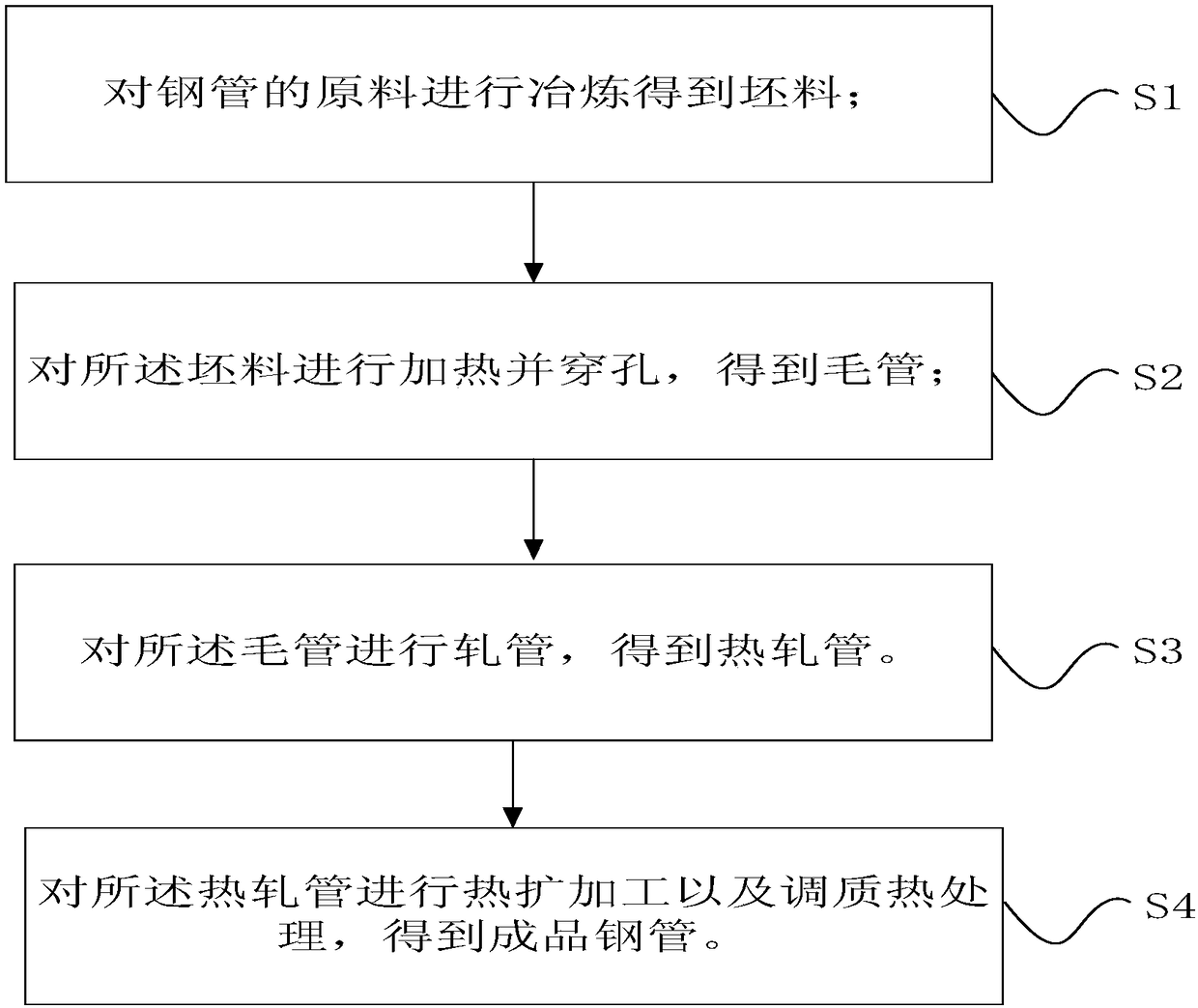
[0046] The specific steel pipe production process includes:

[0047] Step S1, smelting the raw material of the steel pipe to obtain a billet.

[0048] Specifically, raw materials are smelted in an electric furnace, refined outside the furnace, vacuum degassed and arc-shaped continuous casting to obtain billets.

[0049] Step S2, heating the above-mentioned blank, and then piercing with a tapered roller to obtain a capillary tube.

[0050] Specifically, firstly, the billet is heated, and the heating process includes a preheating stage, a heating stage I, a heating stage II, a heating stage III, a soaking stage I and a soaking stage II. The time of each stage is 10min, 15min, 25min, 20min, 20min and 10min respectively. Specifically, after heating...

Embodiment 2

[0059] The difference from Example 1 is that the raw material of the steel pipe includes 0.25% of C, 0.15% of Si, 1.70% of Mn, 0.01% of P, 0.011% of S, 0.04% of Ti and 0.0005% of b. The C equivalent is 0.59%. In addition, in the process of tempering and tempering the above-mentioned pre-tube to obtain the above-mentioned finished steel pipe, the heating temperature is 930° C., the holding time is 10 minutes, and the above-mentioned pre-tube after water cooling and quenching is tempered at 670° C. Air cooling after heat preservation for 40 minutes to obtain the above-mentioned finished steel pipe.

Embodiment 3

[0061] The difference from Example 1 is that the raw material of the steel pipe includes 0.29% C, 0.30% Si, 1.53% Mn, 0.014% P, 0.005% S, 0.024% Ti and 0.0016% B. The C equivalent is 0.596%. In addition, in the process of tempering and heat-treating the above-mentioned pre-tube to obtain the above-mentioned finished steel pipe, the heating temperature is 920°C, the holding time is 15min, and the above-mentioned pre-tube after water cooling and quenching is tempered at 640°C, After heat preservation for 60 minutes, it was air-cooled to obtain the above-mentioned finished steel pipe.


PUM

PropertyMeasurementUnit
Yield strengthaaaaaaaaaa

Abstract

The invention provides a steel pipe, raw materials and manufacturing method thereof, and a drill rod for a rotary drilling rig. The raw materials of the steel pipe comprise, by weight, 0.25-0.33% of C, 0.15-0.50% of Si, 1.30-1.70% of Mn, 0.020% or the less of P, 0.015% or the less of S, 0.012-0.04% of Ti, 0.0005-0.0030% of B and the balance Fe and inevitable impurities. In the raw materials of thesteel pipe, the content of C is 0.25-0.33%, and it is ensured that the formed steel pipe has certain yield strength and the good welding property; the content of Mn is 1.30-1.70%, the solution strengthening effect can be achieved better, thus the yield strength of the steel pipe is improved, and the hardenability of steel is improved through the appropriate amount of Ti and B; and the yield strength of the steel pipe formed through the raw materials can reach 550 MPa or above.

Description

technical field [0001] The present application relates to the field of steel pipes, in particular, to a steel pipe, its raw materials, its production method and a drill pipe for a rotary drilling rig. Background technique [0002] Rotary drilling rig is a construction machine suitable for hole-forming operations in building foundation engineering. It is mainly suitable for construction in soil layers such as sandy soil, cohesive soil and silty soil. Widely used in foundation construction. [0003] Due to its high efficiency and low pollution, rotary drilling rigs have become the main construction equipment for large-scale buildings, railways and expressway bridge pile foundations at home and abroad. With the increase of national infrastructure investment, the demand for rotary drilling rigs has surged. [0004] The drill pipe for rotary drilling rig is the key component of rotary drilling rig. The drill pipe for rotary drilling rig is composed of several sections of steel ...

Claims


Application Information

Patent Timeline
IPC IPC(8): C22C38/02C22C38/04C22C38/14B21C37/06C21D9/08C21D1/18E21B17/00
CPCB21C37/06C21D1/18C21D9/08C22C38/02C22C38/04C22C38/14C22C38/32E21B17/00
Inventor 凌仲秋周勇赵勤范其良郭海明赵映辉孙群保朱智禄张敏黄佑启孙群峰刘启增
Owner 衡阳华菱连轧管有限公司
Why Eureka
Try Eureka