Intelligent multifunctional horizontal directional drilling machine

A horizontal directional drilling rig, multi-functional technology, applied in the direction of directional drilling, drill pipe, drill pipe, etc., can solve the problems of low construction efficiency, inability to adapt, high worker intensity, etc., to ensure stability and safety, improve rod replacement efficiency, The effect of improving construction efficiency

Pending Publication Date: 2018-09-28
福建亿钻机械有限公司
View PDF9 Cites 5 Cited by
  • Summary
  • Abstract
  • Description
  • Claims
  • Application Information

AI Technical Summary

Problems solved by technology

This kind of equipment is generally suitable for steel pipes and PE pipes with a pipe diameter of φ300~φ1200mm, and the maximum laying length can reach 1500m. It is suitable for various soil conditions from soft soil to hard rock, and has broad application prospects; Increase the connection of drill pipes to ensure the feed of the drill pipes, and these drill pipes also need to be recovered after the operation is completed. The existing horizontal directional drilling rigs mainly rely on manual or cranes to carry or lift the drill pipes. The former is time-consuming and labor-intensive. If it is too large, the construction efficiency is low; the latter is difficult to accurately lift the drill pipe to the designated position, and the efficiency is also very low; in addition, the existing horizontal directional drilling rig has a single control mode and cannot meet the needs of some special occasions; There are horizontal directional drilling rigs that cannot provide external power supply, and the supporting auxiliary equipment in the construction needs to be equipped with another gasoline generator to generate power and provide power. This method is inconvenient to use and high in cost

Method used


Image

  • Intelligent multifunctional horizontal directional drilling machine
  • Intelligent multifunctional horizontal directional drilling machine
  • Intelligent multifunctional horizontal directional drilling machine

Examples


Embodiment Construction

[0039] The present invention will be described in detail below in conjunction with the accompanying drawings and specific embodiments.

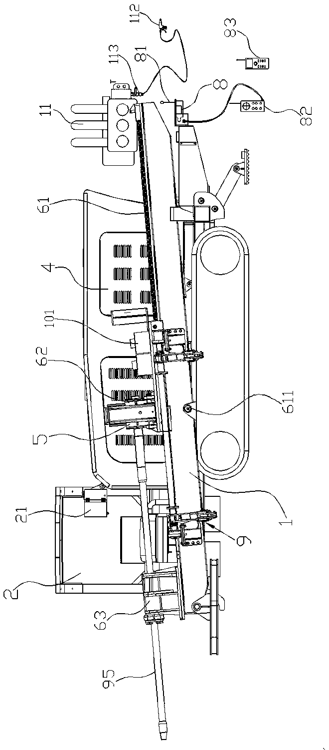
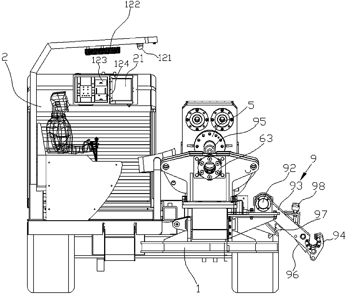
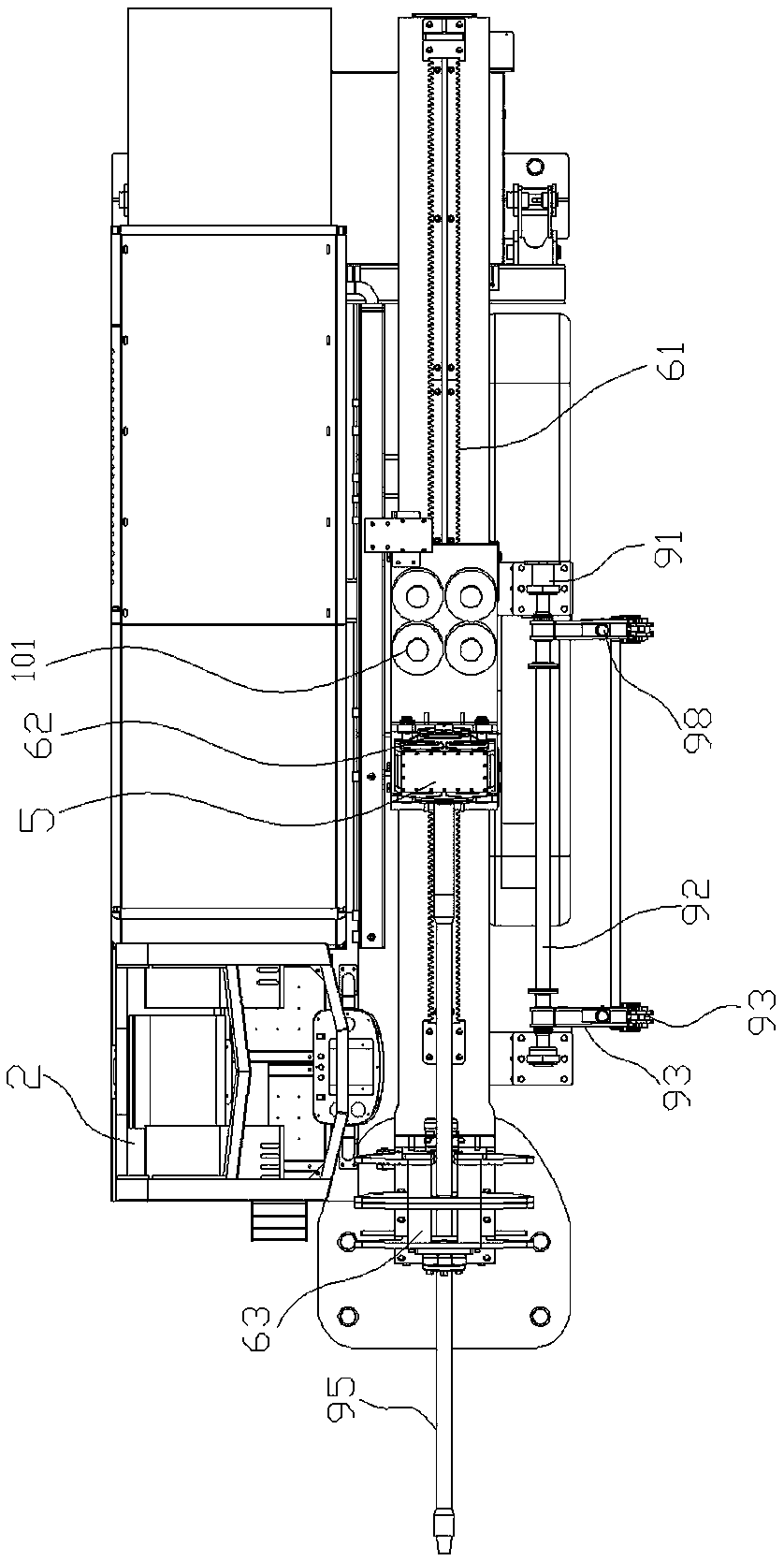
[0040] see Figure 1 to Figure 6 , an intelligent multifunctional horizontal directional drilling machine, including:

[0041] Walking chassis 1;

[0042] The power system 4 is installed on the walking chassis 1 to provide power for the horizontal directional drilling machine;

[0043] The rack 61 is installed on the walking chassis 1, and is vertically rotatably connected with the chassis 1 through a rotating shaft 611, and drives the rack 61 to rotate up and down through a hydraulic rod to change the vertical inclination of the rack 61;

[0044] The drive platform 15 can move back and forth along the rack 61;

[0045] The drilling tool 5 is installed on the driving platform, and clamps the rear end of the drilling rod 95;

[0046] The main engine 62 is installed on the driving platform to drive the drilling tool 5 to rotate, thereby dri...


PUM


Abstract

The invention relates to an intelligent multifunctional horizontal directional drilling machine. The intelligent multifunctional horizontal directional drilling machine comprises a walking chassis, apower system, a rack rail, a driving platform, a drilling tool, a main engine, a push-pull system and a guide disk. The power system is installed on the walking chassis and provides power for the horizontal directional drilling machine. The rack rail is obliquely forwards and downwards fixed to the walking chassis. The driving platform moves along the rack rail. The drilling tool is mounted on thedriving platform to clamp the rear end of a drill rod. The main engine is mounted on the driving platform to drive the drilling tool to rotate, thereby driving the drill rod to carry out rotating feeding. The push-pull system is installed on the driving platform and includes an even number of hydraulic driving systems symmetrically disposed on both sides of the rack rail. The hydraulic driving systems include first hydraulic motors, reducers and gears, after the first hydraulic motors are decelerated by the reducers, the first hydraulic motors drive the gears to rotate, and the gears separately mesh with the rack rail. The guide disk is disposed on a chassis at the front of the main engine to guide the feeding direction of the drill tool.

Description

technical field [0001] The invention relates to an intelligent multifunctional horizontal directional drilling machine, which belongs to the field of non-excavation pipe laying machinery. Background technique [0002] Horizontal directional drilling rig is a construction machine for laying various underground utilities (pipes, cables, etc.) without excavating the ground surface. In construction, it is suitable for sandy soil, clay, pebbles and other ground conditions, and it can be constructed in most non-hard rock areas in my country. The working environment temperature is -15℃~+45℃. Horizontal directional drilling technology is a new construction technology that combines directional drilling technology in the petroleum industry with traditional pipeline construction methods. It has the advantages of fast construction speed, high construction precision, and low cost. It is widely used in water supply, Gas, electricity, telecommunications, natural gas, oil and other pipelin...

Claims


Application Information

Patent Timeline
Patent Type & Authority Applications(China)
IPC IPC(8): E21B7/02E21B7/04E21B19/16E21B19/083F02B63/04
CPCE21B7/02E21B7/046E21B19/083E21B19/164F02B63/04
Inventor 张兴禄施兴林梁延
Owner 福建亿钻机械有限公司
Why Eureka
Try Eureka