A method for continuous arrangement of working face in mining area of ​​rock burst and high gas mine

A technology of ground pressure shock and layout method, which is used in surface mining, gas discharge, underground mining, etc., can solve the problems of large amount of tunnel engineering, low production efficiency, complex production system, etc. The effect of high efficiency and simple production system

Active Publication Date: 2019-07-02
中煤西安设计工程有限责任公司
View PDF8 Cites 0 Cited by
  • Summary
  • Abstract
  • Description
  • Claims
  • Application Information

AI Technical Summary

Problems solved by technology

[0003] The purpose of the present invention is to adopt one well multi-area in the current rockburst and high gas mine, mining, excavation are phase-separated, and the production continuation tension, Due to the practical problems of large engineering volume, complex production system, high production cost, and low production efficiency, a method for continuous layout of working faces in mining areas of rock burst and high gas mines is proposed, which is divided by reasonable zoning in mining areas. , realize the linked mining of mining, excavation, and pumping in the mining area, avoid the high investment, tense connection, and low efficiency caused by skip mining layout in the traditional mining area, and also avoid the coal resource loss caused by leaving large coal pillars in the section (4) waste

Method used


Image

  • A method for continuous arrangement of working face in mining area of ​​rock burst and high gas mine
  • A method for continuous arrangement of working face in mining area of ​​rock burst and high gas mine
  • A method for continuous arrangement of working face in mining area of ​​rock burst and high gas mine

Examples


Embodiment Construction

[0029] In order to make the purpose, technical solutions and advantages of the patent embodiments of the present invention clearer, the technical solutions in the embodiments of the present invention will be clearly and completely described below in conjunction with the accompanying drawings in the embodiments of the present invention. Obviously, the described implementation Examples are some embodiments of the present invention, not all embodiments. Based on the embodiments of the present invention, all other embodiments obtained by persons of ordinary skill in the art without creative efforts fall within the protection scope of the present invention.

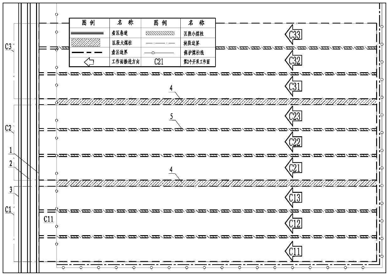
[0030] Such as figure 1 Shown, a kind of rock burst provided by the present invention and working face continuation arrangement method in the mining area of ​​high gas mine comprise: at first select the production mining area, the production mining area is perpendicular to the mining area roadway (respectively mining area auxi...


PUM


Abstract

The invention discloses a method for continued arrangement of a working face in a mining area of rock burst and high gas mine. The method comprises the following steps that the mining area is selectedand is divided into three zones, each zone is divided into a plurality of sections, and the mining sequence of the sections is determined; a first zone primary mining working face is mined firstly, and at the same time the second zone primary mining working face and third zone primary mining working face are separately subjected to gas pre-drainage and heading work; after stoping of the first zone primary mining working face is completed, a heading end of the third zone is moved to a second face of the first zone, and the roadway heading is carried out; the stoping of the second zone primarymining working face is carried out; the third zone primary mining working face is subjected to gas pre-drainage; and so on, the heading, pre-drainage and stoping work are separately carried out simultaneously in the three zones, and cycling is carried out until the next mining area continues. Linkage of mining, heading and pumping in the mining area is achieved, the method for continued arrangement of the working face in the mining area of rock burst and high gas mine has the advantages of less development (preparation), less investment, concentrated production, less occupancy of personnel andequipment, and the contradiction between rock burst and tight connection in the high gas mine can be can effectively alleviated.

Description

technical field [0001] The invention belongs to the technical field of mining engineering, and in particular relates to a method for continuously arranging working faces in mining areas of rock burst and high gas mines. Background technique [0002] At the present stage, in order to meet the requirements of prevention and control of rock burst mines in my country, the mining area of ​​the mine is divided into single-wing mining areas for mining, small coal pillars (4-8m) are reserved between the working face sections for mining, the working face is mined sequentially, and the adjacent working face roadways are mined Arrangement along the goaf roadway, or leave large coal pillars (40-80m) in the mining area, and because the "Coal Mine Safety Regulations" (2016 Edition) has a clear limit on the safety distance between mining and excavation, in order to solve the mine Conflict between mining and excavation, two or three mining areas are often opened at the same time for jump mini...

Claims


Application Information

Patent Timeline
Patent Type & Authority Patents(China)
IPC IPC(8): E21C41/18E21F7/00
CPCE21C41/18E21F7/00
Inventor 盛超王长友华召文刘清宝孙东飞李伟赵传刚郭建南张鸥
Owner 中煤西安设计工程有限责任公司
Why Eureka
Try Eureka