Engine catalytic converter with novel expansion pipe flow guiding device and sepiolite carrier

A technology of catalytic converter and flow guiding device, which is applied to engine components, machines/engines, mufflers, etc., can solve the problems of small specific surface area, high production cost of catalytic converters, single catalytic reaction, etc., and achieve large specific surface area. , Improve the utilization rate and service life, and eliminate the effect of local flow loss

Active Publication Date: 2018-09-28
XIANGTAN UNIV
View PDF6 Cites 4 Cited by
  • Summary
  • Abstract
  • Description
  • Claims
  • Application Information

AI Technical Summary

Problems solved by technology

More importantly, the catalytic coating of the traditional catalytic converter carrier uses noble metal materials, which only have a single catalytic reaction, and its specific surface area is small, so it needs to load a large amount of precious metals to meet higher emission standards, which makes the catalytic converter higher production costs

Method used


Image

  • Engine catalytic converter with novel expansion pipe flow guiding device and sepiolite carrier
  • Engine catalytic converter with novel expansion pipe flow guiding device and sepiolite carrier
  • Engine catalytic converter with novel expansion pipe flow guiding device and sepiolite carrier

Examples


Embodiment Construction

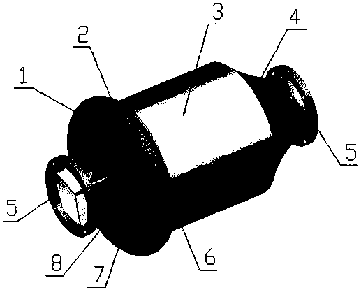
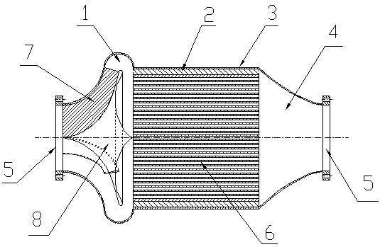
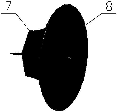
[0021] Such as Figure 1-Figure 4 As shown, a kind of engine catalytic converter that has novel expansion pipe flow guiding device and sepiolite carrier of the present invention is composed of flange 5, expansion pipe 1, flow guiding device 8, fixed rib plate 7, housing 3, shock absorption Layer 2, sepiolite carrier 6 and shrink tube 4; the inlet end of the expansion tube 1 is connected to the flange 5, the inlet end of the expansion tube 1 is connected to the outlet end of the exhaust pipe through the flange, and a flow guiding device is arranged in the expansion tube 1 8. The deflector 8 is located in the expansion tube 1, and is fixed on the inner wall of the expansion tube 1 through the fixed rib plate 7. There are three fixed rib plates 7, the upper long side of which is welded on the inner wall of the expansion tube 1, and the lower long side is welded on the guide tube 1. On the front wall of the flow device 8, the outlet end of the expansion tube 1 is connected to one ...


PUM


Abstract

The invention relates to an engine catalytic converter with a novel expansion pipe flow guiding device and a sepiolite carrier. The engine catalytic converter is composed of a flange, an expansion pipe, the flow guiding device, a fixing rib plate, a shell, a vibration reduction layer, the sepiolite carrier and a shrinkage pipe. The expansion pipe is of a smooth streamline curved surface structure,local flow losses generated inside the expansion pipe are eliminated, and a curved surface bent segment at the tail of the expansion pipe is used for changing the flow direction of tail gas. The expansion pipe is internally provided with the flow guiding device; and the inner wall of the expansion pipe cooperates with the outer wall of the flow guiding device to guide flow of the tail gas, so that gas flow are more uniform in flow distribution when passing through the sepiolite carrier. The fixing rib plate is added, and the flow guiding device is fixed to the inner wall of the expansion pipe. The engine catalytic converter is applicable to purification, conducted under different working conditions, of the tail gas of a gasoline engine or a diesel engine and also applicable to ceramic honeycomb carriers and metal carriers of different hole densities and in different hole shapes; sepiolite is added to a carrier catalyst coating material, and compound conversion efficiency of the tail gas is improved; the streamline curved surface is adopted for the shrinkage pipe, and the flow resistance inside the shrinkage pipe is reduced; and the engine catalytic converter is simple in structure.

Description

technical field [0001] The invention relates to an engine catalytic converter, in particular to an engine catalytic converter with a novel expansion tube guide device and a sepiolite carrier. Background technique [0002] In traditional engine catalytic converters, the expansion tube is designed as a circular truncated structure with a straight-sided curved surface and a gradually increasing cross-section. The disadvantage is that when the exhaust gas enters the expansion tube, it is easy to form a vortex near the wall of the expansion tube and separate the gas wall. Phenomena such as these cause a large local flow loss inside the expansion tube, and at the same time cause the vehicle exhaust at the front end of the carrier to be unevenly distributed in the radial direction. The central area of ​​the carrier of the traditional catalytic converter is prone to rapid aging due to the large flow and high temperature due to the large flow rate and large thermal stress generated, ...

Claims


Application Information

Patent Timeline
Patent Type & Authority Applications(China)
IPC IPC(8): F01N3/28
CPCF01N3/2803F01N3/2842F01N3/2892F01N2260/06
Inventor 张建平申欣左青松刘庭显龚曙光王树森
Owner XIANGTAN UNIV
Why Eureka
Try Eureka