
Boiler smoke recirculation system and method

A recirculation system and boiler flue gas technology, applied in the boiler flue gas recirculation system and combustion field, can solve the problems of difficult nitrogen oxide concentration, increase boiler operating cost, pollution, etc., to reduce emissions and improve pollution. Problems, the effect of flexible operation

Pending Publication Date: 2018-09-28
TSINGHUA UNIV
View PDF0 Cites 3 Cited by
  • Summary
  • Abstract
  • Description
  • Claims
  • Application Information

AI Technical Summary

Problems solved by technology

[0002] The concentration of nitrogen oxides has a strong correlation with the generation of PM2.5, which causes smog. Most coal-fired power plants in China have completed ultra-low emission transformation, that is, nitrogen oxides (NO x ) concentration below 50mg / Nm 3 , but with the strengthening of national environmental protection efforts, it is more difficult to further reduce the concentration of nitrogen oxides in boiler flue gas
Severe contamination occurs during the combustion of high-alkali metal fuel in the boiler, and the current pollution prevention and control measures will greatly increase the operating cost of the boiler

Method used


Image

  • Boiler smoke recirculation system and method
  • Boiler smoke recirculation system and method
  • Boiler smoke recirculation system and method

Examples


Embodiment Construction

[0023] The specific embodiment of the present invention and working process will be further described below in conjunction with accompanying drawing.

[0024] The orientation terms such as up, down, left, right, front and rear in this application document are established based on the positional relationship shown in the drawings. If the drawings are different, the corresponding positional relationship may also change accordingly, so this should not be understood as limiting the scope of protection.

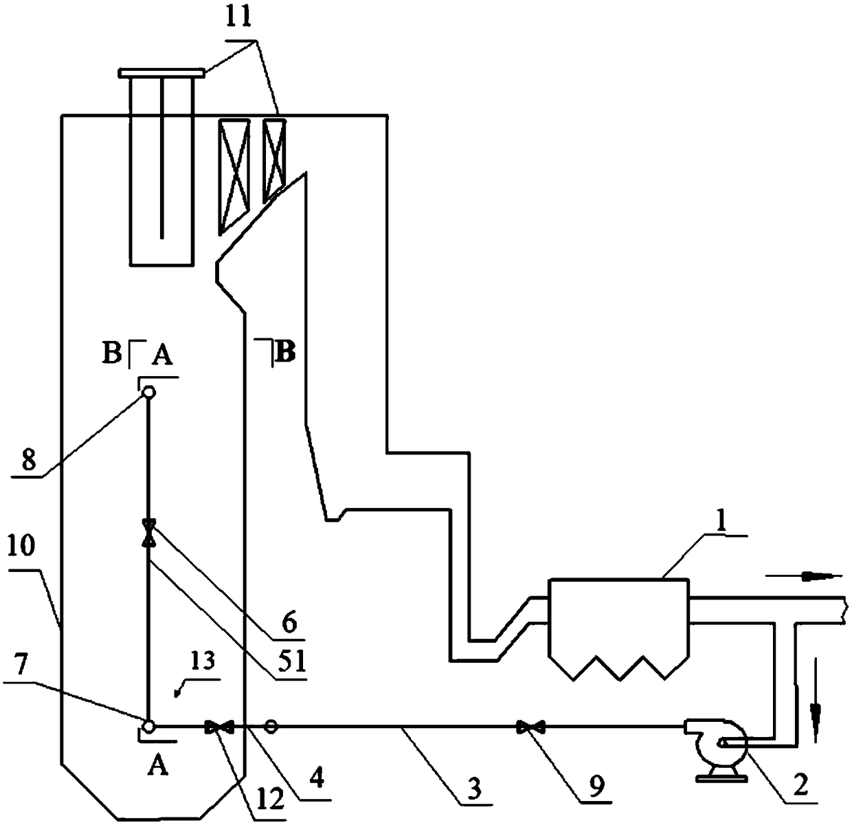
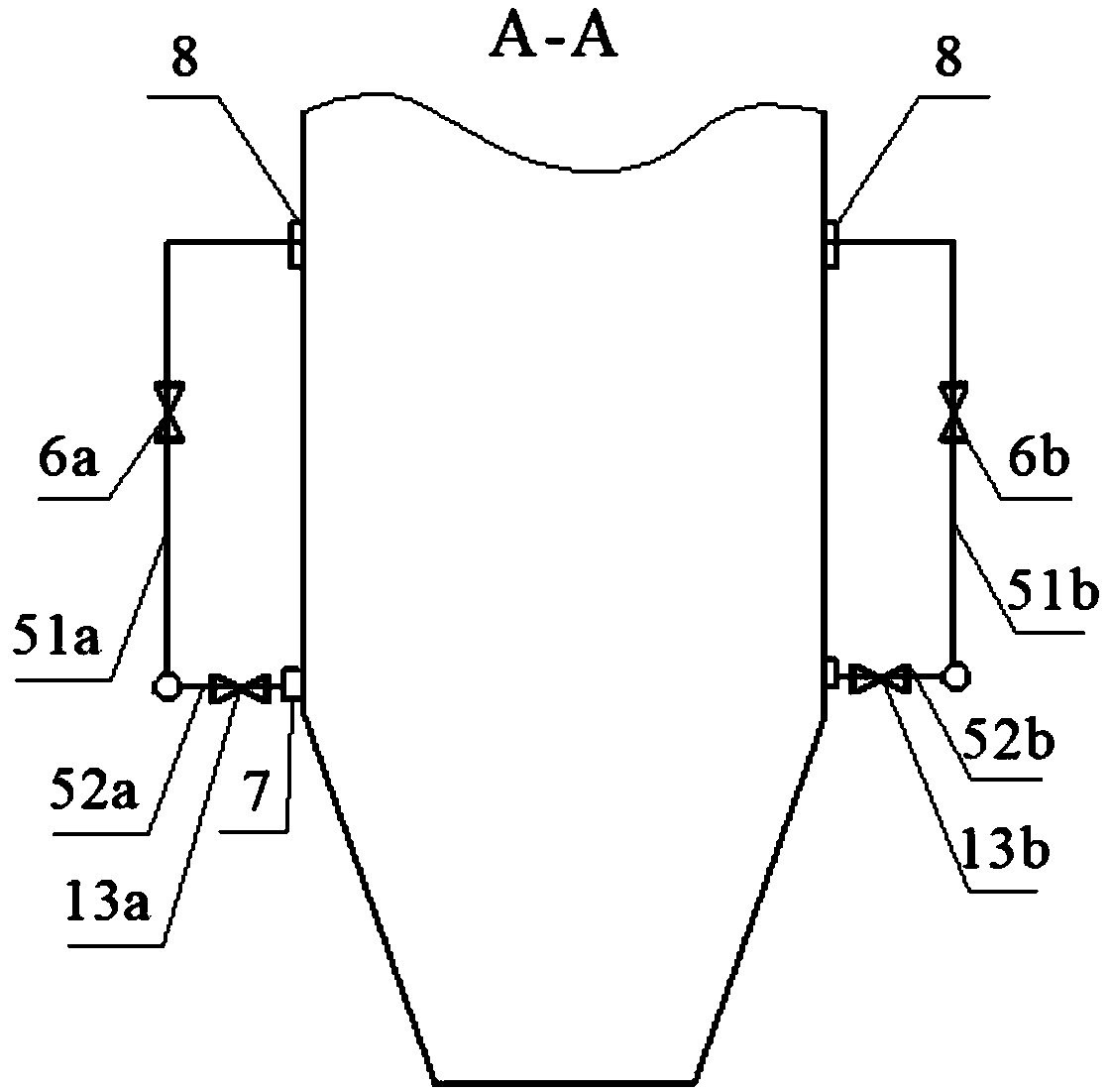
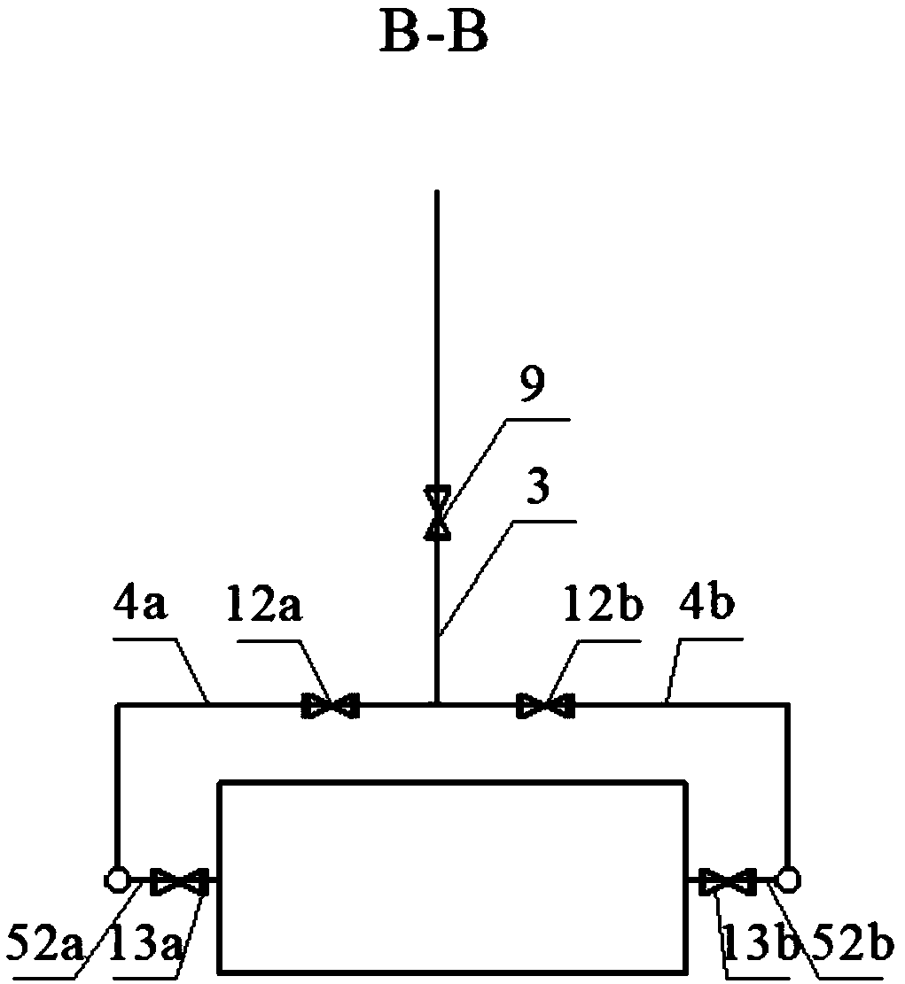
[0025] Such as figure 1 As shown, a boiler flue gas recirculation system includes a fan 2, a main air duct 3, a sub-air duct 4, and a nozzle group 5, etc. The system can be used to return flue gas from the boiler dust collector 1 outlet to the boiler furnace 10 . The last-stage burn-out air outlet on the upper part of the furnace 10 is the OFA air supply port 8, and the last-stage burn-out air usually refers to the burn-out air or secondary air at the highest part of the furnace...


PUM


Abstract

A boiler smoke recirculation system comprises a draught fan, a main air pipe, auxiliary air pipes, spray pipe groups and the like. The draught fan is arranged on the main air pipe. The start end of the main air pipe is connected with an outlet of a dust collector. The tail end of the main air pipe is located outside the lower portion of a hearth of a boiler. The auxiliary air pipes are connected to the tail end of the main air pipe. The spray pipe groups are connected to the tail ends of the auxiliary air pipes and each comprise an upper spray pipe and a lower spray pipe. An opening of each upper spray pipe is arranged at an OFA supply opening of the upper portion of the hearth of the boiler. An opening of each lower spray pipe is arranged at a primary air opening of the hearth of the boiler. The flow of recirculation smoke is adjusted through a main air valve. The recirculation rate of the recirculation smoke is made to be 10-30%. The recirculation smoke is adjusted and distributed byan upper air valve and / or a lower air valve so that the ratio between the amount of the smoke entering the hearth via the upper spray pipes and the amount of the smoke entering the hearth via the lower spray pipes is 2:8-8:2. By the adoption of the boiler smoke recirculation system, through adjustment of the recirculation rate of the smoke and adjustment of the flow ratio between upper smoke andlower smoke of the hearth, the flame temperature and the outlet temperature of the hearth are effectively adjusted, and operation is flexible and easy; and emission of nitrogen oxides is reduced, andthe contamination problem caused by combustion of high-alkali metal fuel is relieved.

Description

technical field [0001] The invention relates to a boiler flue gas recirculation system and a method thereof, belonging to the technical field of combustion technology. Background technique [0002] The concentration of nitrogen oxides has a strong correlation with the generation of PM2.5, which causes smog. Most coal-fired power plants in China have completed ultra-low emission transformation, that is, nitrogen oxides (NO x ) concentration below 50mg / Nm 3 , but with the strengthening of national environmental protection efforts, it is more difficult to further reduce the concentration of nitrogen oxides in boiler flue gas. Severe contamination occurs during the combustion of high-alkali metal fuels in boilers. The current pollution prevention and control measures will greatly increase the operating costs of boilers. [0003] A large number of practices have shown that reducing the boiler flame temperature can help reduce nitrogen oxides (NO x ), and reducing the temperatu...

Claims


Application Information

Patent Timeline
Patent Type & Authority Applications(China)
IPC IPC(8): F23C9/08
CPCF23C9/08
Inventor 肖寒吴玉新吕俊复刘青
Owner TSINGHUA UNIV
Learn More