
A device and method for detecting the cross-sectional bending profile of a planar bending sheet metal part

A technology of plane bending and sheet metal parts, applied in measuring devices, optical devices, instruments, etc., can solve the problems of complex data acquisition and processing, poor accuracy of contour size data, high labor intensity, etc., and achieve convenient and efficient detection process. The effect of fast response and improved efficiency

Active Publication Date: 2019-11-22
YANSHAN UNIV
View PDF1 Cites 0 Cited by
  • Summary
  • Abstract
  • Description
  • Claims
  • Application Information

AI Technical Summary

Problems solved by technology

[0003] Existing contour detection technologies mainly include template processing, manual measurement, etc. The contour dimension data obtained by these measurement methods are poor in accuracy, low in efficiency, and labor-intensive
High-precision three-coordinate measuring instruments, profile scanners and laser scanning inspection technologies often use expensive internal components, and the equipment costs several million yuan, which is difficult for small companies and laboratories to bear.
The contour detection device invented by Publication No. CN104535017B uses two laser two-dimensional scanners, which are distributed in a circle to detect the contour of the workpiece. Not only is the cost high, but the data acquisition and processing are relatively complicated

Method used


Image

  • A device and method for detecting the cross-sectional bending profile of a planar bending sheet metal part
  • A device and method for detecting the cross-sectional bending profile of a planar bending sheet metal part
  • A device and method for detecting the cross-sectional bending profile of a planar bending sheet metal part

Examples


Embodiment Construction

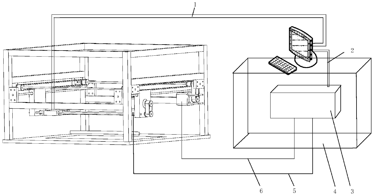
[0035] exist figure 2 In the schematic diagram of the detection device for bending contours of plane bending sheet metal parts shown, the detection device includes two parts: a mechanical device and a control device. Connect via Ethernet line 2, PLC connects to X module servo motor 20 via signal line A5, connects to Y module servo motor 16 via signal line via signal line B6, and connects to computer via data line 1 in the mechanical device. connect;

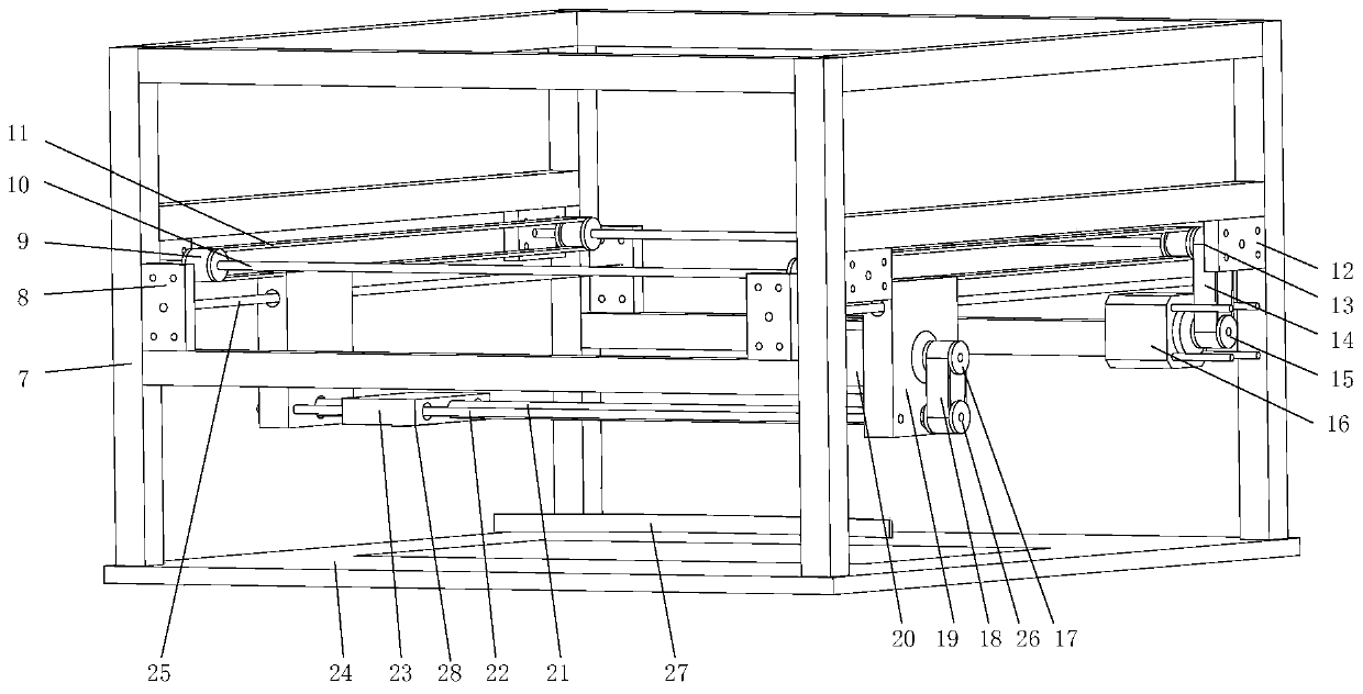
[0036] exist image 3 , Figure 4 , Figure 5 In the schematic diagram of the mechanical device for detecting the bending profile of a plane bending sheet metal part, the frame 7 is a cuboid frame in which the aluminum profiles are fixed by screws. The X-direction translation module and the Y-direction translation module are arranged inside the frame. The bottom of the frame is equipped with The workpiece supporting plate 24 fixedly connected with it is equipped with a light source system under the workpiece supporting plate...


PUM


Abstract

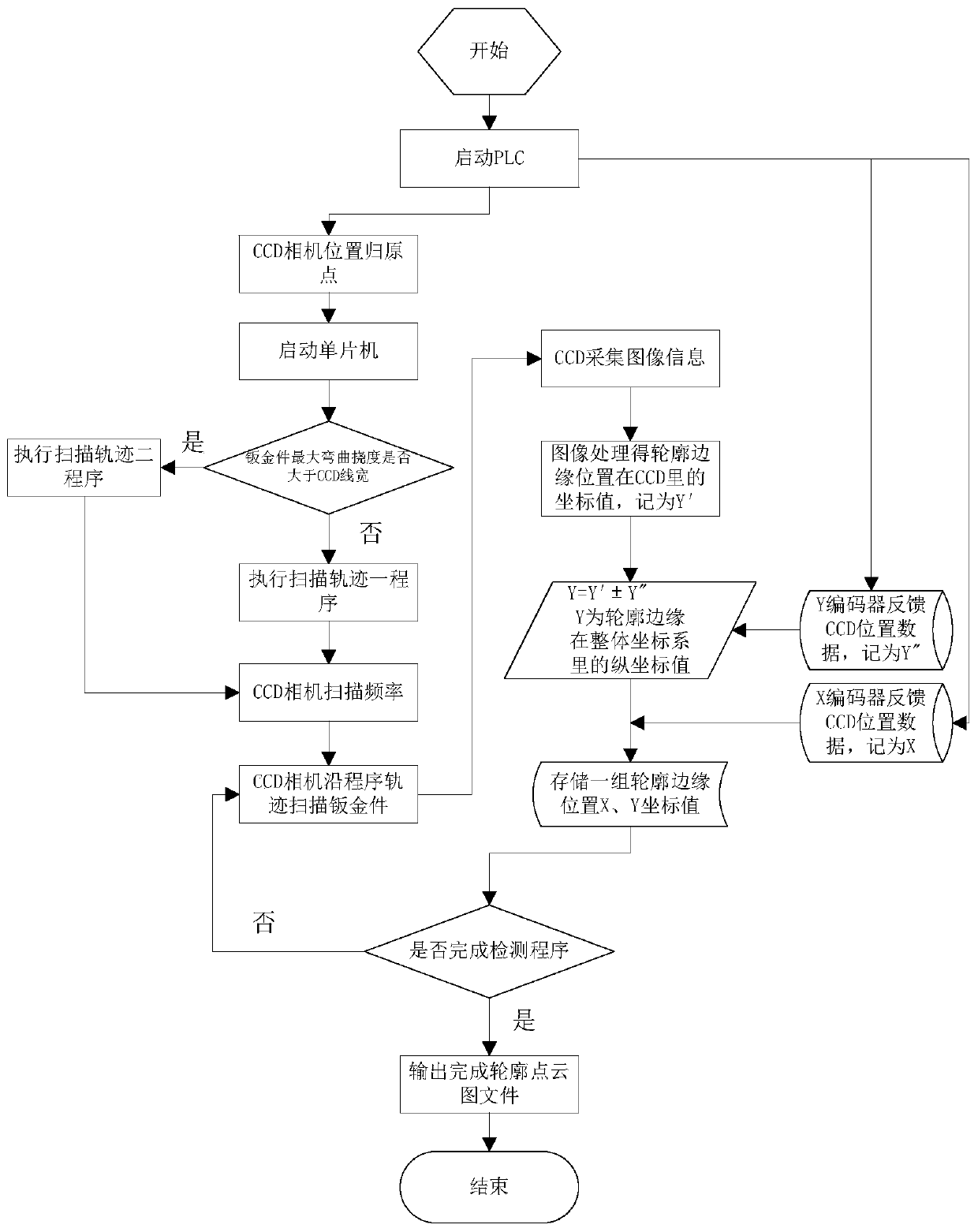
Provided is a device for detecting the curved contour of a section of the planar bent sheet metal part. The device comprises a mechanical device and a control device. The control device comprises a control box, a PLC, a single-chip microcomputer and a computer. The mechanical device comprises a frame, an X-direction translation module, a Y-direction translation module and a linear array CCD camera. A detecting method adopting the detecting device mainly comprises the steps the contour position information collected by the linear array CCD camera and Y-module coder data of the mechanical deviceare combined and serve as a Y coordinate value of a metal plate contour two-dimensional diagram after data processing, position data fed back by a X-module servo motor coder in the mechanical deviceis adopted as an X coordinate value of the metal plate contour two-dimensional diagram, metal plate contour circulating scanning and contour point data collection are completed through control of a driving program, and a two-dimensional point cloud file related to the curved contour of the sheet metal part is obtained after upper computer data processing is carried out. The device is automatic, efficient and cheap and can extract contour data fast and conveniently.

Description

technical field [0001] The invention belongs to the technical field of mechanical detection, and in particular relates to a device and method for detecting the contour of a sheet metal part. Background technique [0002] Sheet metal parts with different bending shapes are usually used in the mechanical and industrial fields. Sheet metal parts with special shape contours are usually obtained by bending the sheet metal through a stretch bending machine for many times to obtain a curve consistent with the target contour. However, in each stretch bending, the sheet will have a corresponding rebound, and the target profile cannot be obtained in one stretch bending, which requires multiple times of variable mold profile curve stretch bending on the stretch bending machine to obtain the final target profile. Therefore, after each stretch bending, it is necessary to detect the curvature of the sheet metal contour, and through the data processing and calculation of the contour curve,...

Claims


Application Information

Patent Timeline
Patent Type & Authority Patents(China)
IPC IPC(8): G01B11/24
CPCG01B11/24
Inventor 马瑞穆振凯翟瑞雪
Owner YANSHAN UNIV
Learn More