Thin-wall part working modal parameter determining method and system

A technology for determining the working mode and parameters, which is applied in image data processing, measuring devices, instruments, etc., can solve the problems of difficulty in meeting the requirements of low-cost working mode testing, low efficiency and precision, and high requirements for the measurement environment and preliminary work , to achieve the effect of improving calculation efficiency and low measurement accuracy, solving difficult identification, measurement environment and preliminary work requirements

Inactive Publication Date: 2018-09-28
HUNAN UNIV OF SCI & TECH
View PDF7 Cites 16 Cited by
  • Summary
  • Abstract
  • Description
  • Claims
  • Application Information

AI Technical Summary

Problems solved by technology

Typical machine vision vibration test methods generally require auxiliary structured light and pasted signs. This method has relatively high requirements for equipment, measurement environment and preliminary work, and it is difficult to meet the requirements of low-cost working modal testing.
In

Method used


Image

  • Thin-wall part working modal parameter determining method and system
  • Thin-wall part working modal parameter determining method and system
  • Thin-wall part working modal parameter determining method and system

Examples


Embodiment 2

[0128] by Figure 5 The cantilever beam shown in is the object. According to the method provided by the present invention, 15 strong feature points are sequentially selected along the y direction on the cantilever beam as optical flow matching tracking points. The response signal of the optical flow matching tracking point is divided into 13 segments for correlation function calculation, that is, the correlation function is averaged 13 times. Assume that the reference channel is the channel numbered 15, that is, feature point 15 is used as the reference point. Figure 6 To select the response signals of three measuring points under random pulse excitation. Depend on Figure 7 From the average correlation function in , it can be seen that the response signal represented by it is smoother and has more obvious attenuation characteristics, and it can obtain more accurate results by replacing the original response signal.

[0129] In order to determine the correct modal order an...


PUM


Abstract

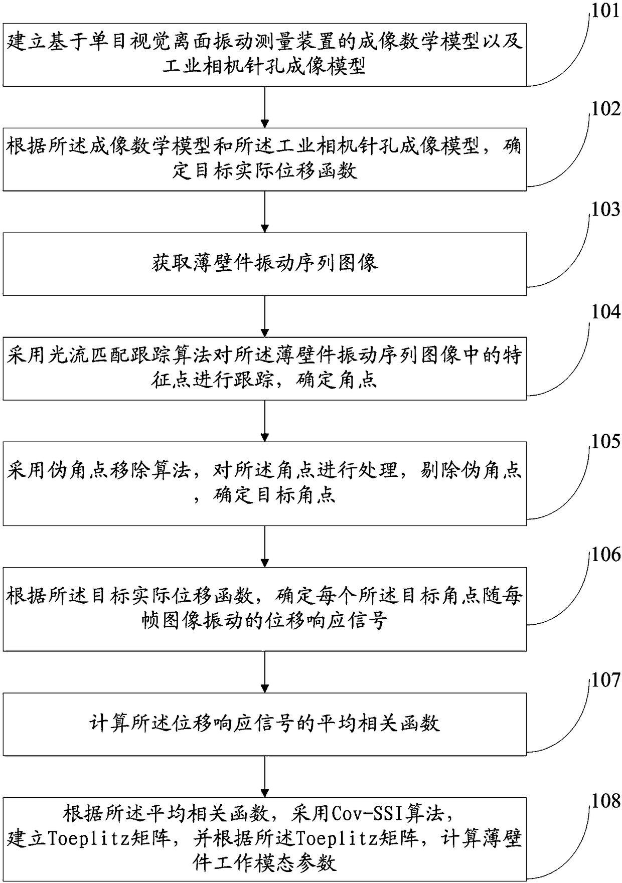
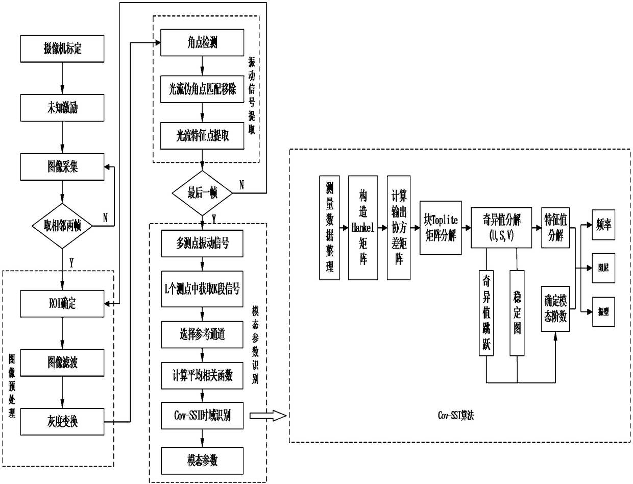
The invention discloses a thin-wall part working modal parameter determining method and system. The method comprises the following steps: establishing an imaging mathematical model based on a monocular vision off-plane vibration measuring device, and an industrial camera pinhole imaging model, determining a target actual displacement function, continuously tracking target angle points by utilizingan optical flow matching tracking algorithm with the pseudo-angle point removal, and obtaining a displacement response signal for each target angle point to vibrate along with each frame of image, calculating the average correlation function of each displacement response signal, and replacing the displacement response signal with the mean correlation function to serve as the Cov-SSI algorithm input item to carry out the working modal parameter identification, so that the working modal test of the thin-walled part is realized. According to the method, auxiliary structure light is not needed, any labels or marks are not needed to be pasted, and multi-view non-contact vibration mode measurement can be achieved, the problem that the calculation efficiency and the measurement precision of themachine vision vibration mode measurement method are low is effectively solved, and the problem that a low signal-to-noise ratio working mode parameter is difficult to identify is well solved.

Description

technical field [0001] The invention relates to the field of measurement of working mode parameters of thin-walled parts, in particular to a method and system for determining working mode parameters of thin-walled parts based on monocular visual optical flow tracking. Background technique [0002] Thin-walled parts have many advantages such as light weight, compact structure and strong bearing capacity, and have been widely used in various industrial fields. However, thin-walled parts also have the characteristics of low rigidity, weak strength and large size, which are prone to vibration and deformation, causing problems such as noise and instability, and even serious mechanical failures, resulting in major safety accidents. Therefore, it is necessary to carry out thin-walled parts efficiently and accurately. Vibration modal parameter identification of wall parts. However, for those thin-walled parts that cannot be artificially excited or the excitation size cannot be meas...

Claims


Application Information

Patent Timeline
IPC IPC(8): G01H9/00G06T7/00
CPCG01H9/00G06T7/0004G06T2207/10052G06T2207/20016
Inventor 伍济钢邵俊蒋勉周根王刚李鸿光
Owner HUNAN UNIV OF SCI & TECH
Why Eureka
Try Eureka