Graphene plasmonic gas sensor

A plasmon and graphene technology, applied in the field of infrared optical sensing, can solve problems such as detection of difficult gas samples

Inactive Publication Date: 2018-09-28
THE NAT CENT FOR NANOSCI & TECH NCNST OF CHINA
View PDF7 Cites 4 Cited by
  • Summary
  • Abstract
  • Description
  • Claims
  • Application Information

AI Technical Summary

Problems solved by technology

[0005] However, at present, graphene plasmons are still difficult to be used in the detection of gas samples. The main challenge is that there is no suitable sensor that can combine infrared light-transmitting micro-nano gas chambers with graphene plasmonic devices.

Method used


Image

  • Graphene plasmonic gas sensor
  • Graphene plasmonic gas sensor
  • Graphene plasmonic gas sensor

Examples


Embodiment 1

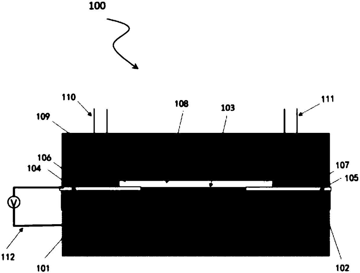
[0042] figure 1 Shown is a cross-sectional view of the graphene plasmonic gas sensor according to the first embodiment of the present invention. According to the first embodiment of the present invention, the graphene plasmonic gas sensor 100 in this embodiment includes sequentially from bottom to top Substrate 101, dielectric layer 102, graphene layer 103, microcavity 108, and cover plate 109,

[0043] Wherein the two ends of the graphene layer 103 are respectively provided with a metal electrode 104 and a metal electrode 105, wherein the metal electrode 104 and the metal electrode 105 are selected from chromium, titanium, iron, aluminum, copper, gold, silver, platinum.

[0044] The two ends of the microcavity 108 are respectively provided with a patterned coating 106 forming a microcavity channel and a patterned coating 107 forming a microcavity channel; the thickness of the microcavity 108 is in the range of 10-200 nm.

[0045] Wherein the cover plate 109 is respectively p...

Embodiment 2

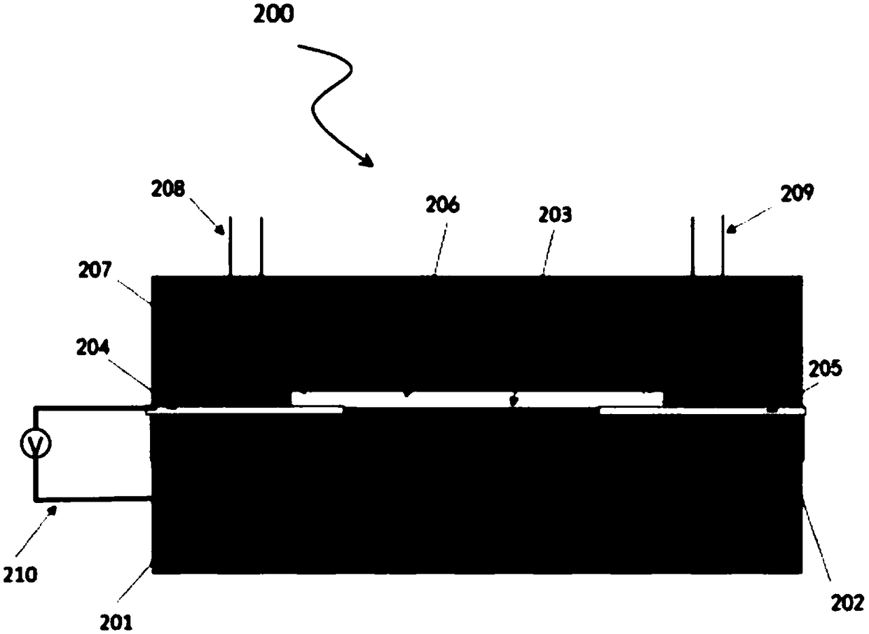
[0061] figure 2 A schematic structural diagram (sectional view) of the graphene plasmonic gas sensor according to the second embodiment of the present invention is shown.

[0062] Wherein the graphene plasmonic gas sensor 200 in this embodiment includes a substrate 201, a dielectric layer 202, a graphene layer 203, a microcavity 206, and a cover plate 207 in sequence from bottom to top,

[0063] Wherein the two ends of the graphene layer 203 are respectively provided with a metal electrode 204 and a metal electrode 205;

[0064] Wherein the cover plate 207 is respectively provided with a sample inlet channel 208 and a sample outlet channel 209 communicated with the microcavity 206;

[0065] The substrate 201 is connected to the metal electrode 204 or the metal electrode 205 through a gate voltage source 210 .

Embodiment 3

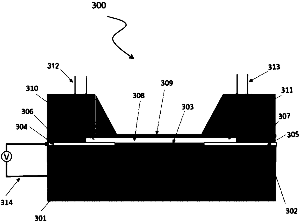
[0067] image 3 A schematic structural diagram (sectional view) of the graphene plasmonic gas sensor according to the third embodiment of the present invention is shown.

[0068] Wherein the graphene plasmonic gas sensor 300 in this embodiment includes a substrate 3201, a dielectric layer 302, a graphene layer 303, an infrared window 309, a microcavity 308, and a cover plate 310 and a cover plate 311 from bottom to top,

[0069] Wherein the two ends of the graphene layer 303 are respectively provided with a metal electrode 304 and a metal electrode 305;

[0070] Wherein the sample inlet channel 312 and the sample outlet channel 313 communicated with the microcavity 308 are respectively set on the cover plate 310 and the cover plate 311;

[0071] Wherein the substrate 301 is connected to the metal electrode 304 or the metal electrode 305 through a gate voltage source 314;

[0072] Wherein the infrared window 309 includes a SiN window, which can transmit infrared light.

[00...


PUM

PropertyMeasurementUnit
thicknessaaaaaaaaaa
thicknessaaaaaaaaaa
thicknessaaaaaaaaaa

Abstract

The invention discloses a graphene plasmonic gas sensor. The sensor comprises a substrate, a dielectric layer, a graphene layer, a microcavity and a cover plate in sequence from bottom to top, whereina sample injection channel and a sample discharge channel communicating with the microcavity are respectively disposed in the cover plate; according to the invention, a gas microcavity is above the graphene layer, and the graphene plasmon can interact with gas molecules to obtain a plasmon-enhanced gas infrared spectrum, and realize the identification of gas species; at the same time, the sensorcan detect a very small amount of the gas molecules with a plasmon wavelength in the mid-infrared band (resonance frequency is 400 to 3000 wavenumbers); and the sensor can be reused and integrated.

Description

technical field [0001] The invention relates to the fields of infrared optical sensing, gas sensing and plasmon enhanced spectroscopy, in particular to a gas sensor integrating graphene plasmonic devices and microcavities. Background technique [0002] Gas sensing can be used to detect various flammable, explosive, toxic gases and gas phase product monitoring of biological and chemical reactions, and has important applications in the fields of environmental detection, security, chemical and medical diagnosis. For example, in medical diagnosis, early disease diagnosis can be carried out through the content of NO, isopropanol and ammonia in the exhaled gas of the human body: the exhaled gas of patients with chronic obstructive pulmonary disease contains about 5000ppb NO; the exhaled gas of lung cancer patients The content of isopropanol in alcohol exceeds 100ppb; the content of ammonia in the exhaled gas of patients with renal failure exceeds 3000ppb. Commonly used electrical...

Claims


Application Information

Patent Timeline
Patent Type & Authority Applications(China)
IPC IPC(8): G01N21/3504
CPCG01N21/3504
Inventor 戴庆杨晓霞胡海郭相东胡德波
Owner THE NAT CENT FOR NANOSCI & TECH NCNST OF CHINA
Why Eureka
Try Eureka