HUD (head up display) light path system capable of reducing TFT (thin-film transistor) sunlight pollution
An optical path system and solar light technology, applied in the field of HUD, can solve the problems of pixel brightness changes, acceleration, device threshold drift, etc.
- Summary
- Abstract
- Description
- Claims
- Application Information
AI Technical Summary
Problems solved by technology
Method used
Image

Examples
Embodiment 1
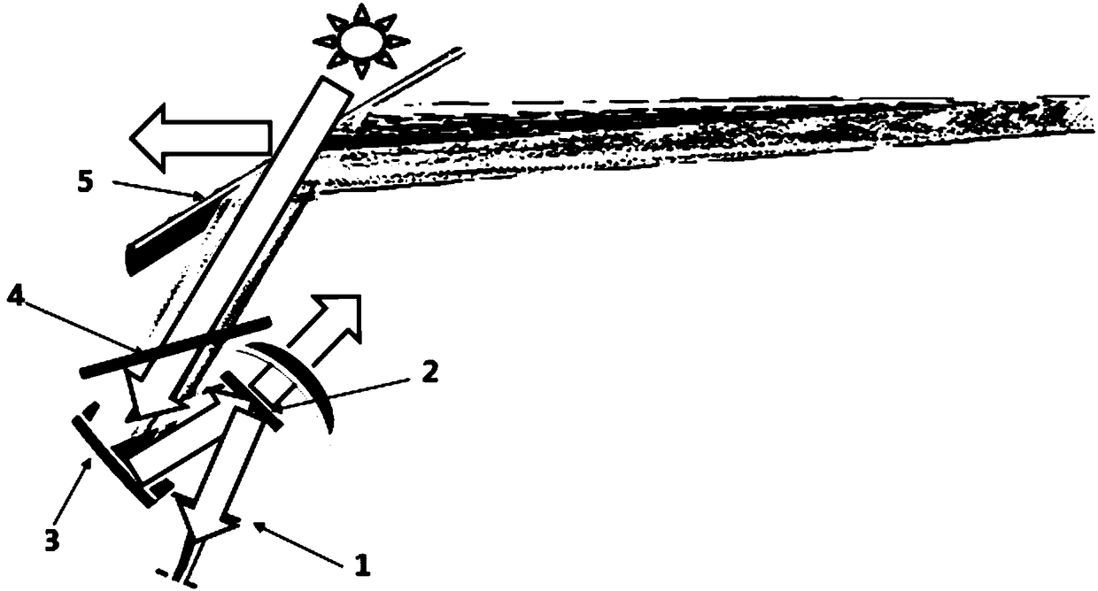
[0019] A light path structure diagram of a HUD light path system for reducing TFT solar light pollution provided by Embodiment 1 of the present invention, as shown in figure 1 As shown, there is a TFT1 fixed in the emission direction of the emission source, and also includes a reflector 2, a free-form surface mirror 3, a dust-proof film 4 and a windshield glass 5 that sequentially form a transflective optical path;
[0020] In this embodiment, the reflector 2 is a polarized reflector such as PBS, and the dustproof film 4 is an ordinary dustproof film 4 .
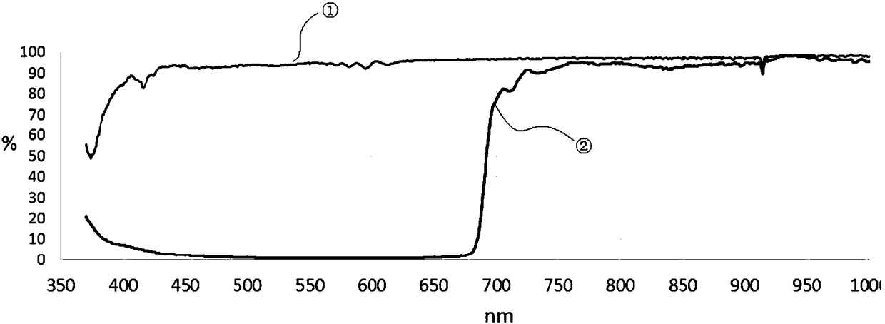
[0021] Optionally, sunlight enters the TFT along the reverse optical path of the reflected optical path, taking CMF as an example, as figure 2 As shown, where: the abscissa represents the wavelength of light, 420nm ~ 680nm is the visible light part, and greater than 680nm is the infrared part; the ordinate represents the light transmittance; line ① represents P light, and line ② represents S light. from figure 2 It can b...
Embodiment 2
[0024] The optical path structure diagram of a HUD optical path system for reducing TFT solar light pollution provided by Embodiment 2 of the present invention, see again figure 1 , The difference between this embodiment and Embodiment 1 is that: the reflector 2 is an ordinary reflector, and the dustproof film 4 is a polarizing film such as DBEF-QV2 of 3M Company.
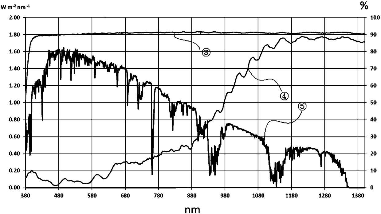
[0025] like figure 2 The DBEF-QV2 spectrum curve diagram shown, in which: the abscissa represents the wavelength of light, 420nm ~ 680nm is the visible light part, and greater than 680nm is the infrared part; the left ordinate represents the solar energy, and the right ordinate represents the light transmittance; line ③ , ④ represent the sunlight transmission curve, line ⑤ represents the spectrum curve. It can be seen from line ③ that about 90% of visible light and infrared light pass through, and about 10% of reflected light. From line ④, it can be seen that almost all visible light is reflected, with reflectivi...
PUM
 Abstract
Description
Claims
Application Information
PatSnap Eureka turns technology decisions into work you can execute. Powered by our Innovation Knowledge Graph, it runs expert workflows across engineering, life sciences, materials and intellectual property. Get your review-ready output in minutes.


