Method of manufacturing micro convex lens by using PDMS

A micro-convex lens, SU-8 technology, applied in the photoplate process of lens, pattern surface, optics, etc., can solve the problems of difficult control of geometric size, easy deformation of sphere, difficult mass production of glass bead lenses, etc.

Inactive Publication Date: 2018-09-28
GUANGXI UNIV FOR NATITIES
View PDF4 Cites 6 Cited by
  • Summary
  • Abstract
  • Description
  • Claims
  • Application Information

AI Technical Summary

Problems solved by technology

A glass bead with a diameter of 2 mm has a magnification of about 150 times, which meets the common scientific observation requirements. However, the spherical lens made of a fused glass rod is difficult to control the geometric size, and the sphere is easy to absorb under the action of gravity. deformation, and the third is that there may be bubbles during the melting process, so it is ultimately difficult to mass-produce such glass bead lenses

Method used


Image

  • Method of manufacturing micro convex lens by using PDMS

Examples


Embodiment 1

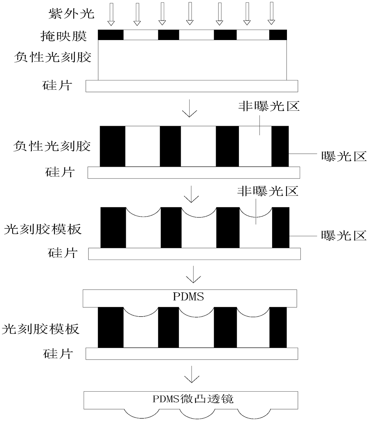
[0043] A method of utilizing PDMS to make a 100-fold magnification micro-convex lens, comprising the following steps:

[0044] Step (1): Clean and dry the silicon wafer, that is, first use the RCA cleaning process to clean the silicon wafer, and then place the silicon wafer on a high-temperature heating plate to thoroughly dry the moisture on the surface of the silicon wafer;

[0045] Step (2): Coating, that is, coating a layer of negative photoresist with a uniform thickness on the top surface of the silicon wafer by using the spin coating method, and the negative photoresist is SU-8 negative photoresist 2025 series, the spin coating method refers to uniformly coating negative photoresist on the top surface of the silicon wafer by a spin coater, while preventing bubbles from appearing in the photoresist, and using the self-leveling effect of the photoresist to statically Set aside for 40 minutes to remove the ripples generated by spin coating; when coating, the spin coating m...

Embodiment 2

[0059] A kind of method that utilizes PDMS to make micro-convex lens with magnification 200 times, comprises the following steps:

[0060] Step (1): Clean and dry the silicon wafer, that is, first use the RCA cleaning process to clean the silicon wafer, and then place the silicon wafer on a high-temperature heating plate to thoroughly dry the moisture on the surface of the silicon wafer;

[0061] Step (2): Coating, that is, coating a layer of negative photoresist with a uniform thickness on the top surface of the silicon wafer by using the spin coating method, and the negative photoresist is SU-8 negative photoresist 2150 series, the spin coating method refers to uniformly coating negative photoresist on the top surface of the silicon wafer by a spin coater, while preventing bubbles from appearing in the photoresist, and using the self-leveling effect of the photoresist to statically Set aside for 50 minutes to remove the ripples produced by spin coating; when coating, the spi...

Embodiment 3

[0075] A kind of method utilizing PDMS to make 300 times magnification micro-convex lens, comprises the following steps:

[0076] Step (1): Clean and dry the silicon wafer, that is, first use the RCA cleaning process to clean the silicon wafer, and then place the silicon wafer on a high-temperature heating plate to thoroughly dry the moisture on the surface of the silicon wafer;

[0077] Step (2): Coating, that is, coating a layer of negative photoresist with a uniform thickness on the top surface of the silicon wafer by using the spin coating method, and the negative photoresist is SU-8 negative photoresist 3035 series, the spin coating method refers to uniformly coating negative photoresist on the top surface of the silicon wafer by a spin coater, while preventing bubbles from appearing in the photoresist, and using the self-leveling effect of the photoresist to statically The ripples produced by spin coating can be removed after 45 minutes; when coating, the spin coating ma...


PUM

PropertyMeasurementUnit
Thicknessaaaaaaaaaa

Abstract

The invention relates to the technical field of manufacture of lenses, and specifically relates to a method of manufacturing a micro convex lens by using PDMS. The method comprises the following sevensteps of washing and drying a silicon sheet, gluing, baking before photoetching, photoetching, baking after photoetching, manufacturing the micro convex lens, and detecting a focal length of the micro convex lens. In the method, a photoresist plate with a top surface of micro concave lens surface is manufactured through steps of baking twice and exposing negative photoresist in ultraviolet, and the PDMS material is copied onto the top surface of the photoresist plate so as to manufacture the micro convex lens installed on a simple microscope. The difference between an actual value of the focal length of the micro convex lens and a theoretical calculation value is less than 5%, so that the micro convex lens fully meets the use requirement of an object mirror of a simple microscope, has theadvantages of being low in manufacture cost, being easy to manufacture, and being produced in large scale, and can be widely used in fields like science and education.

Description

technical field [0001] The invention relates to the technical field of lens production, in particular to a method for producing a micro-convex lens by using PDMS. Background technique [0002] Due to the large differences in the specifications of optical lenses, high precision in external dimensions, small size, and small curvature errors, high-precision lenses require sophisticated processing equipment and testing instruments to be produced. According to the application requirements in the field of science education, a magnification of 100-300 times can meet the teaching requirements. Therefore, in recent years, a glass bead microscope with low precision but simpler manufacturing technology has attracted widespread attention in the industry. The preparation method is The slender glass rod is melted with a high-temperature flame, and spherical droplets appear under the action of surface tension, and after cooling, glass beads with a small diameter are formed. A glass bead w...

Claims


Application Information

Patent Timeline
IPC IPC(8): G03F7/00G02B3/00
CPCG02B3/00G03F7/0005G03F7/0035
Inventor 李耀俊
Owner GUANGXI UNIV FOR NATITIES
Why Eureka
Try Eureka