Contact network failure risk assessment method based on binary decision graph algorithm
A binary decision diagram and risk assessment technology, applied in the field of catenary failure risk assessment based on binary decision diagram algorithm, can solve the problems of few catenary failure risk assessment methods, increased resource requirements, time-consuming and labor-intensive, etc. Combined explosions, simplified calculations, and effects with precise results
- Summary
- Abstract
- Description
- Claims
- Application Information
AI Technical Summary
Problems solved by technology
Method used
Image
Examples
Embodiment 1
[0059] A catenary failure risk assessment method based on a binary decision diagram algorithm, comprising the following steps:
[0060] (1) Generate BDD structure
[0061] 1) Determine system boundaries, basic events and top events;
[0062] 2) Build a fault tree: According to the series-parallel relationship between events in the system, use logic gates to connect the top event with the intermediate events that directly lead to the occurrence of the top event, and then connect the intermediate events with the intermediate events or basic events that directly lead to the occurrence of the intermediate events Connect until the logical connection between the top event and the basic event is completed;
[0063] 3) Normalization of the fault tree: the normalized fault tree only contains three logic gates of "and", "or" and "not". Before generating the BDD, the established fault tree is transformed into a standardized fault tree. The "not" gate can be transformed by Mor...
Embodiment 2
[0104] Generate the BDD structure:
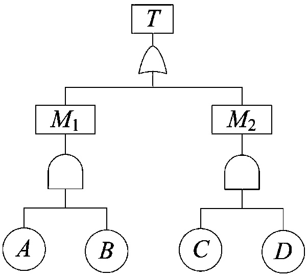
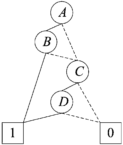
[0105] Fault tree T such as figure 1 As shown, its logical expression is T=M 1 +M 2 =(A·B)+(C·D), the BDD structure of T is as follows figure 2 As shown, this is an efficient and concise structure that can reduce storage redundancy. figure 2 In , the circular node represents the Boolean variable corresponding to the event, 1 in the square represents logical true (bddtrue), and 0 represents logical false (bddfalse). Except for the terminal points "1" and "0", each BDD node is connected to two sub-nodes downwards, and the secondary BDD structure when the node is 1 is obtained along the solid line, and similarly, it can be obtained along the dotted line When it is zero, the secondary BDD structure. from figure 2 It can be seen that if the Boolean variable A is "true", the BDD process will lead to B, if B is also "true", it will lead to the "1" node; if A is "false", the BDD process will lead to C, if C is also "false", the...
Embodiment 3
[0107] In order to make the BDD program simple and reliable, all BDD nodes are objects generated by the BDD node class. The BDD node class definition is shown in Table 1:
[0108] Table 1 Definition of BDD node class
[0109]
[0110] It can be seen from Table 1 that each BDD node can point to two BDD child nodes, including intermediate nodes and terminal nodes "1" and "0".
[0111] Shannon decomposition theorem description: Let f(x 1 ,x 2 ,x 3 ,...,x n ) is a Boolean function, x i (i=1,2,...,n) is any independent variable of f(x), let:
[0112]
[0113]
[0114] then f(x 1 ,x 2 ,x 3 ,...,x n ) can be decomposed into
[0115]
[0116] and Still a Boolean function, you can continue to select the next variable x j (j≠i) is decomposed until it can no longer be decomposed, then the disjointization of the original function can be realized.
PUM
 Abstract
Description
Claims
Application Information
 - R&D
- Intellectual Property
- Life Sciences
- Materials
- Tech Scout
- Unparalleled Data Quality
- Higher Quality Content
- 60% Fewer Hallucinations
Browse by: Latest US Patents, China's latest patents, Technical Efficacy Thesaurus, Application Domain, Technology Topic, Popular Technical Reports.
© 2025 PatSnap. All rights reserved.Legal|Privacy policy|Modern Slavery Act Transparency Statement|Sitemap|About US| Contact US: help@patsnap.com


