Sensorless accurate commutation method and device of brushless DC motor
A brushless DC motor and sensor technology is applied in the field of sensorless precise commutation of brushless DC motors, which can solve the problems of misjudging the commutation signal by a single chip, reducing the operating efficiency and control performance of the system, and achieving stable operation and improving operation. Efficiency and stability, the effect of high system accuracy
- Summary
- Abstract
- Description
- Claims
- Application Information
AI Technical Summary
Problems solved by technology
Method used
Image

Examples
Embodiment Construction
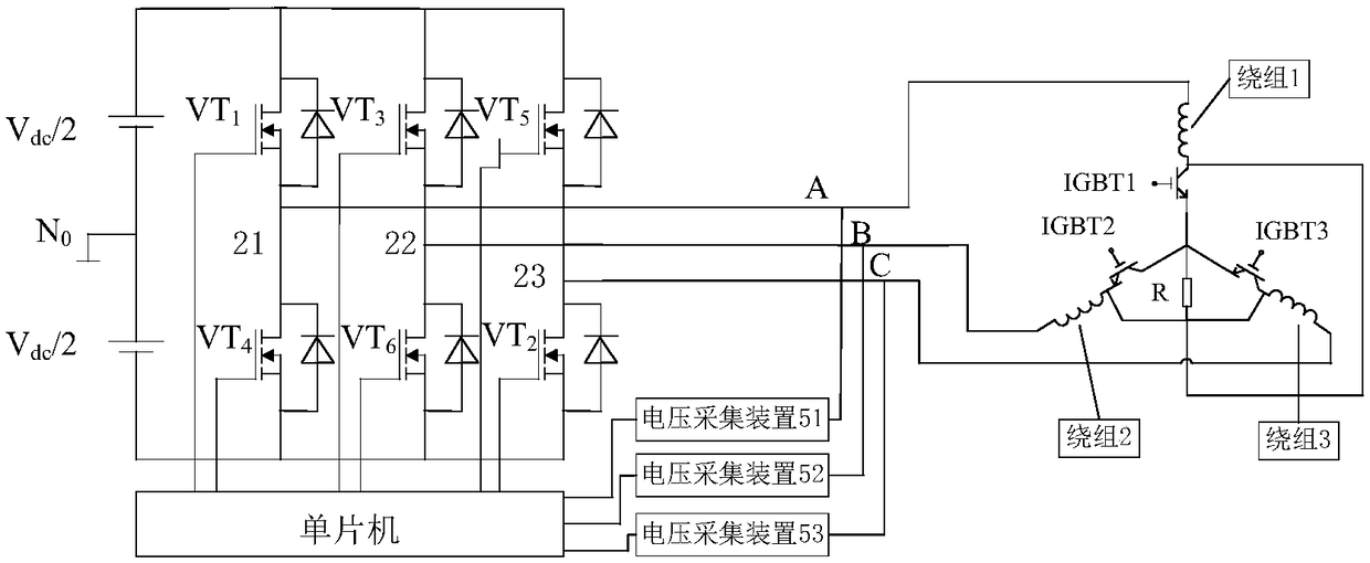
[0024] The technical solutions of the present invention will be described in detail below in conjunction with the accompanying drawings.
[0025] The present invention provides a device for accurate phase commutation of a brushless DC motor without a sensor, which is used for accurately judging the phase commutation time of the brushless DC motor and for accurately judging the phase commutation time of the brushless DC motor. The device includes a DC power supply, Three-phase bridge inverter, new winding, three voltage acquisition devices and single-chip microcomputer, among them, the DC power supply is connected in parallel with the three-phase bridge inverter, and the three output ends of the three-phase bridge inverter are respectively connected to the brushless DC The A-phase, B-phase, and C-phase ports of the new winding of the motor are connected correspondingly; the input ends of the three voltage acquisition devices are respectively connected to the ports of A-phase, B-...
PUM
 Abstract
Description
Claims
Application Information
 - Generate Ideas
- Intellectual Property
- Life Sciences
- Materials
- Tech Scout
- Unparalleled Data Quality
- Higher Quality Content
- 60% Fewer Hallucinations
Browse by: Latest US Patents, China's latest patents, Technical Efficacy Thesaurus, Application Domain, Technology Topic, Popular Technical Reports.
© 2025 PatSnap. All rights reserved.Legal|Privacy policy|Modern Slavery Act Transparency Statement|Sitemap|About US| Contact US: help@patsnap.com