
Single-sided paint spraying room

A technology for painting booths and painting equipment, applied in painting booths, spraying devices, etc., can solve the problems of filter shutdown and other problems, and achieve the effects of reducing labor costs, simple production, and low cost

Pending Publication Date: 2018-10-02
SHANGHAI TONGZHOU MACHINERY EQUIP ENGCO
View PDF1 Cites 1 Cited by
  • Summary
  • Abstract
  • Description
  • Claims
  • Application Information

AI Technical Summary

Problems solved by technology

[0005] In order to solve the problem in the prior art that the filter needs to be replaced frequently and production needs to be stopped during replacement, the purpose of the present invention is to provide a single-side spray booth

Method used


Image

  • Single-sided paint spraying room
  • Single-sided paint spraying room
  • Single-sided paint spraying room

Examples


Embodiment 1

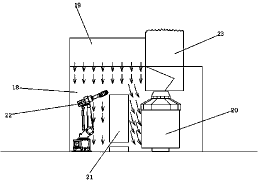
[0048] Such as figure 1 , a kind of one-sided spray booth, comprising a spray booth main body 18, a static pressure chamber 19 connected with the spray booth main body 18 and an exhaust chamber 23, a workpiece 21 is arranged in the paint spray booth main body 18, and a spray paint is arranged on one side of the workpiece 21 Equipment 22 , the other side of the workpiece 21 is provided with a rotary filter device 20 , and the rotary filter device 20 is connected to an exhaust chamber 23 .

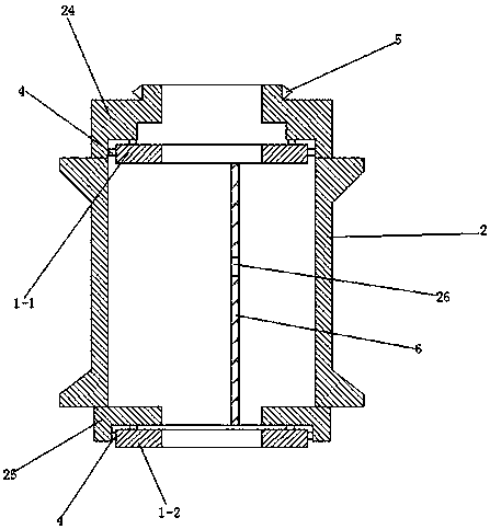
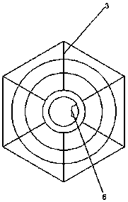
[0049] Such as figure 2 , as shown in 3, the rotary filter device 20 includes a first circular ring 1-1, a second circular ring 1-2 and a filter box set on the outside of the first circular ring 1-1 and the second circular ring 1-2. In the adult 2, the first ring 1-1 and the second ring 1-2 are arranged side by side up and down, and the first ring 1-1 and the second ring 1-2 are respectively symmetrically provided with rollers 4, There are four rollers 4 on the first ring 1-1 and the seco...

Embodiment 2

[0057] Such as Figure 8 As shown, the difference from Embodiment 1 is that the rotary filter device 20 is located outside the main body 18 of the spray booth, and the rotary filter device 20 is connected to the exhaust chamber 23 .

Embodiment 3

[0059] Such as Figure 9 As shown, the difference from Embodiment 1 is that eight interlayers 27 are arranged between every two support rods 3 in the rotary filter device 20 , and the entire filter box assembly 2 is divided into 48 areas for respectively placing filter boxes. The filter boxes are independent of each other. When the filter box needs to be replaced, the filter box is rotated to the position where the baffle plate 6 is located, and the filter box is taken out manually.

[0060] The working principle of the rotary filter device 20: the motor drives the gear ring 5 to rotate through the tooth chain, the filter box assembly 2 rotates under the action of the gear ring 5, and the air containing paint particles enters the box body 8 from the air inlet 14 through the exhaust. Inside, through the gap between the upper support frame 11 and the lower support frame 12, it enters the serpentine filter channel formed by the filter paper 10, wherein the paint particles are tr...


PUM


Abstract

The invention discloses a single-sided paint spraying room which comprises a paint spraying room main body, and a static pressure room and an exhaust room connected to the paint spraying room main body, wherein a workpiece is arranged in the paint spraying room main body, paint spraying equipment is arranged on one side of the workpiece, a rotary filter device is arranged on the other side of theworkpiece, and the rotary filter device is connected to the exhaust room. The single-sided paint spraying room disclosed by the invention is simple in structure, low in cost and free of technical demand on replacing process, does not need professional engineers and lowers the labor cost. The single-sided paint spraying room disclosed by the invention replaces a filter box without halting production, so that the utilization ratio of the single-sided paint spraying room is improved.

Description

technical field [0001] The invention relates to the technical field of painting, in particular to a single-side paint spray booth. Background technique [0002] Painting is the main process in the painting production process. The spray booth is the necessary equipment to complete the painting. It is mainly composed of air supply and exhaust system, paint mist capture and paint residue removal system, and painting equipment. [0003] The spray booth can be divided into double-side spray booth and single-side spray booth. The existing single-side spray booths mainly include water curtain wall type and combined type of water curtain wall and Venturi dripping board. The paint mist capture ability of the water curtain wall type is poor, which will cause great pollution to the wind tower and air conditioning filter behind, and the paint particles will accumulate at the bottom of the spray booth, which will affect the cleanliness and reduce the first pass rate. The combination of...

Claims


Application Information

Patent Timeline
IPC IPC(8): B05B14/43B05B16/60
CPCY02P70/10
Inventor 陆通林
Owner SHANGHAI TONGZHOU MACHINERY EQUIP ENGCO
Learn More