
Defocusing reflection type coupler

A coupler and reflective technology, which is applied in the field of light guide lighting, can solve the problems of large divergence angle of light beams, large optical expansion of LED light sources, and rising costs, so as to achieve uniform distribution of light energy, improve light guide efficiency, and reduce reflection The effect of loss

Active Publication Date: 2018-10-02
ZHEJIANG LIGHTTOWER SAFETY TECH CO LTD
View PDF6 Cites 0 Cited by
  • Summary
  • Abstract
  • Description
  • Claims
  • Application Information

AI Technical Summary

Problems solved by technology

[0002] At present, the optical fiber light guide technology has basically matured in the field of communication, and the optical fiber light guide lighting has been widely used in some low-power decorative lighting, signal lights and endoscopes, but there are still many difficulties in the field of high-power lighting, making it difficult to to promote
[0003] The main technical difficulties of high-power fiber optic light guide lighting are as follows: First, the light-emitting area and light-emitting angle of the LED light source are too large, resulting in a large optical expansion of the LED light source, which is not conducive to optical design; second, the power of the LED light source The density is not high enough, resulting in too many optical fibers and rising costs; third, the luminous characteristics of high-power white LEDs are usually Lambertian-like, and the diameter of the light-guiding optical fiber cannot be too thick (thickness will cause the square exponential increase in the material cost of the optical fiber. ), so that the design of the coupler between the LED chip and the light-guiding fiber is difficult, and the coupling rate is low; Fourth, it is easy to couple high-power white light into the fiber due to the uneven energy distribution and thermal effects (or nonlinear effects) cause fiber optic burnout
Fifth, the divergence angle of the light bundle coupled into the optical fiber is too large, and too many reflections during the light transmission process cause the exponential increase of the reflection loss

Method used


Image

  • Defocusing reflection type coupler
  • Defocusing reflection type coupler
  • Defocusing reflection type coupler

Examples


Embodiment 1

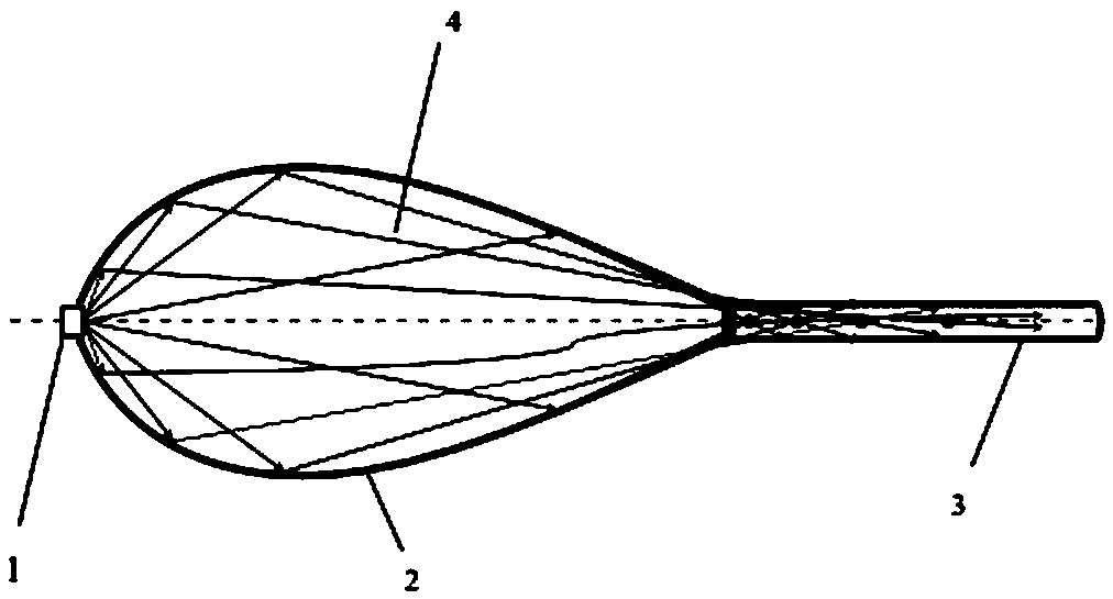
[0029] A defocused reflective coupler such as figure 1 As shown, it includes a coupler 2, and the two ends of the coupler 2 are respectively connected to the LED light source 1 and the optical fiber 3; the inside of the coupler 2 is hollow to form a reflective cavity 4, and the reflective cavity 4 is in the shape of a dewdrop; the inner surface of the coupler 2 has a rotating symmetry.

[0030] The circular bottom of the coupler 2 is fixedly connected to the LED light source 1 , and the top of the tip of the coupler 2 is connected to the optical fiber 3 ; the LED light source 1 and the optical fiber 3 are arranged on the central axis of the coupler 2 .

[0031] The generatrix on the inner surface of the coupler 2 is continuous and smooth, and the curvature distribution is characterized by a monotonous distribution of large LED light source segments and small optical fiber ends.

[0032] The inner surface of the coupler 2 is provided with a reflective film, and the reflective ...


PUM


Abstract

The invention discloses a defocusing reflection type coupler which comprises a coupler body (2). An LED light source (1) and an optical fiber (3) are connected to the two ends of the coupler body (2)correspondingly. The interior of the coupler body (2) is hollowed to form a reflection cavity (4) which is in a dewdrop shape. The inner surface of the coupler body (2) has rotation symmetry. The defocusing reflection type coupler is simple in structure, low in cost, convenient to use and capable of achieving high-efficiency light coupling and ensuring uniform distribution of light rays in the light guide optical fiber, so that the optical fiber energy transmission efficiency is improved, and the optical fiber is prevented from being damaged.

Description

technical field [0001] The invention relates to the technical field of light guide lighting, in particular to a defocused reflective coupler. Background technique [0002] At present, the optical fiber light guide technology has basically matured in the field of communication, and the optical fiber light guide lighting has been widely used in some low-power decorative lighting, signal lights and endoscopes, but there are still many difficulties in the field of high-power lighting, making it difficult to promote. [0003] The main technical difficulties of high-power fiber optic light guide lighting are as follows: First, the light-emitting area and light-emitting angle of the LED light source are too large, resulting in a large optical expansion of the LED light source, which is not conducive to optical design; second, the power of the LED light source The density is not high enough, resulting in too many optical fibers and rising costs; third, the luminous characteristics ...

Claims


Application Information

Patent Timeline
Patent Type & Authority Applications(China)
IPC IPC(8): F21K9/20F21V7/09F21V8/00F21Y115/10
CPCF21K9/20F21V7/09F21V2200/17F21Y2115/10Y02P60/14
Inventor 张航陆建东刘锐符建陈利春
Owner ZHEJIANG LIGHTTOWER SAFETY TECH CO LTD
Features
  • Generate Ideas
  • Intellectual Property
  • Life Sciences
  • Materials
  • Tech Scout
  • Unparalleled Data Quality
  • Higher Quality Content
  • 60% Fewer Hallucinations
Learn More